Austausch der Kurbeln am SRM S975 Powermeter

2012 habe ich einen SRM SRAM S975 GXP Powermeter gekauft und verwende ihn zum Radtraining. Damals hatte ich eine Kurbellänge von 175mm bestellt. Nach knapp zwei Jahren im Einsatz und nach Rücksprache mit meinem Bike Fitter habe ich mich dazu entschlossen, kürzere Kurbeln zu verwenden. Diese bewirken, dass die Knie am oberen Totpunkt der Kurbelumdrehung tiefer stehen. Damit öffnet sich der Hüftwinkel (zwischen Oberschenkel und Wirbelsäule), sodass die stark nach vorne gebeugte Triathlon-Position komfortabler wird und Gefäße weniger stark geklemmt werden.

Die Anschaffung eines neuen Powermeters mit kürzeren Kurbeln wollte ich natürlich vermeiden. Beim SRM S975 Powermeter kann man zum Glück die Kurbeln selber austauschen, als Basis dient eine im Handel verfügbare SRAM S900 Kurbel. Die rechte Kurbel ist mit drei Schrauben am Spider, der Messelektronik enthält, befestigt.

Diese drei Schrauben werden mit einem Torx T25 Schlüssel gelöst.

Nach dem Lösen der Schrauben kann die Kurbel inkl. Achse einfach abgezogen werden.

Die neue Kurbel wird durch den Spider hindurchgeschoben…

…und die Schrauben mit einem Anzugsmoment von 8 Nm angezogen.

Danach kann die Kurbel wieder am Rahmen montiert werden. Die gesamte Prozedur hat 15 Minuten gedauert, inkl. einer groben Reinigung. Nach der Montage sind noch drei Dinge zu beachten:

  1. Die Steigung des Powermeters hat sich durch die Veränderung der Kurbellänge ebenfalls geändert. Somit ist eine Kalibrierung notwendig, der im Powermeter gespeicherte Wert kann wie hier beschrieben mittels eines Garmin Edge Computers aktualisiert werden.
  2. Die Sattelhöhe muss um das Maß der Kurbellängen-Veränderung erhöht (bei Kurbel-Verkürzung) bzw. abgesenkt (bei Kurbel-Verlängerung) werden.
  3. Falls der Hüftwinkel vorher schon “erträglich” war, können noch Spacer unter den Extensions bzw. unter dem Vorbau entfernt werden.

Steigung von SRM Wireless Powermeter mit Garmin Edge 500 updaten

Um eine möglichst genaue Leistungsmessung eines Fahrradtrainings zu gewährleisten, müssen zwei Dinge sichergestellt sein:

  1. Korrekte Erfassung der Nullstelle
  2. Korrekte Einstellung der spezifischen Steigung

Den ersten Punkt sollte man vor jedem Training abgleichen. Bei Garmin heißt das entsprechende Menü “Kalibrierung”, auch wenn das eigentlich nicht ganz präzise ist. Den zweiten Punkt muss man nur bei Veränderungen des Powermeters (bspw. andere Kettenblätter, veränderte Kurbellänge) bzw. in längeren Zeitabständen berechnen und einstellen. Zur Berechnung der Steigung benötigt man ein Prüfgewicht von mindestens 20kg Gewicht und führt damit den unter diesem Link beschriebenen Prozess durch.

Die somit ermittelte spezifische Steigung muss dann noch im Powermeter gespeichert werden, damit sie korrekt an das entsprechende Aufzeichnungsgerät übertragen wird. Der Garmin Edge 500 Fahrradcomputer bietet genau diese Möglichkeit, die im Powermeter gespeicherte spezifische Steigung zu aktualisieren, sodass etwaige Änderungen der Steigung auch bei anderen Aufzeichnungsgeräten “ankommen”. In diesem kurzen Tutorial zeige ich, wie dieser Aktualisierungsprozess genau abläuft.

Im linken Bild ist der Ausgangszustand des Slope-Settings im Android-App “IpBike” dokumentiert, der Slope-Wert beträgt 21.1 (Im Screenshot die unterste Zeile). Zum updaten des Slope-Werts verwende ich einen Garmin Edge 500 mit der Firmware-Version 3.30. Wichtig ist, dass der Powermeter während des Update-Vorgangs nur mit dem Garmin Edge und nicht mit anderen Geräten verbunden ist, ansonsten kann es zu einer Fehlermeldung kommen.


20140109_SRM-Slope-Update_Garmin-Edge-500_0120140109_SRM-Slope-Update_Garmin-Edge-500_02

Zunächst den Garmin Edge einschalten, die Taste “Enter” lange drücken. Dann den Menüpunkt “Einstellungen” auswählen und die Taste “Enter” drücken (linkes Bild). Im nächsten Menü “Fahradeinst.” auswählen und wieder “Enter” drücken (rechtes Bild).

20140109_SRM-Slope-Update_Garmin-Edge-500_0320140109_SRM-Slope-Update_Garmin-Edge-500_04

Nun das relevante Fahrrad auswählen, in diesem Fall “Scott Plasma TT”, und dann die Taste “Enter” drücken (linkes Bild). Im nächsten Menü “ANT+ Leistung” auswählen und “Enter” drücken (rechtes Bild).

20140109_SRM-Slope-Update_Garmin-Edge-500_0520140109_SRM-Slope-Update_Garmin-Edge-500_06

Nun “Sensorinfos” auswählen und “Enter” drücken (linkes Bild). Dann “Steigung” auswählen und “Enter” drücken (rechtes Bild).

20140109_SRM-Slope-Update_Garmin-Edge-500_0720140109_SRM-Slope-Update_Garmin-Edge-500_08

Dann die Zahlenwerte eingeben (linkes Bild), abschließend “Fertig” auswählen und “Enter” drücken (rechtes Bild).

20140109_SRM-Slope-Update_Garmin-Edge-500_0920140109_SRM-Slope-Update_Garmin-Edge-500_10

Dann erscheint die Anzeige “Ändere Steig. Von XX.X Nach XX.X” (linkes Bild). Sofort Kurbel schnell vorwärts drehen. Die Trittfrequenz sollte >40 sein. Wenn der Update-Vorgang erfolgreich war, erscheint die Anzeige “Steigung erfolgreich geändert.”. Die Steigung wurde dann nicht nur im Garmin Edge, sondern auch im SRM Powermeter aktualisiert.

20140109_SRM-Slope-Update_Garmin-Edge-500_1120140109_SRM-Slope-Update_Garmin-Edge-500_12

Wenn die Kurbel während des Update-Vorgangs nicht schnell genug gedreht wurde, erscheint unter Umständen die Fehlermeldung “Slope change failed. Retry?”. In diesem Fall “Ja” auswählen und die Kurbel erneut drehen (linkes Bild). Abschließend habe ich den Powermeter mit meinem Smartphone (Sony Xperia Active) verbunden und den Sensorstatus mit dem App IpBike ausgelesen. Im Screenshot sieht man, das der Slope-Wert vom Powermeter übernommen und korrekt an das App übergeben wurde.

20140109_SRM-Slope-Update_Garmin-Edge-500_1420140109_SRM-Slope-Update_Garmin-Edge-500_15

Scott Plasma TT – My new triathlon bike

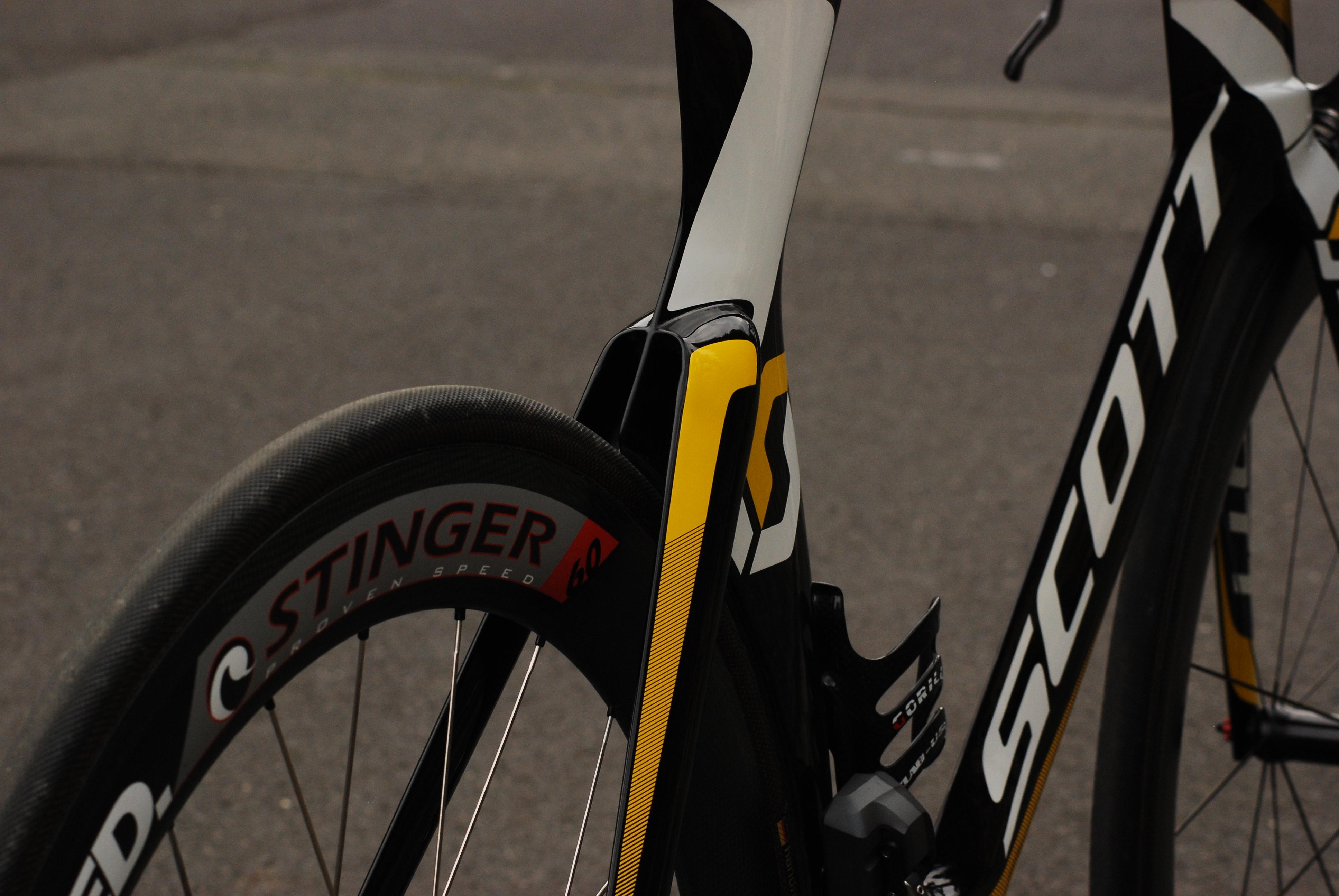
For the last three years, I have been looking for a new triathlon bike. There are lots of fantastic bikes out there, including but not limited to the Cervélo P5, Trek Speed Concept, Specialized Shiv, BMC timemachine TM01, Felt IA, Canyon Speedmax CF and more. After a long lasting and very careful analysis of aerodynamic performance, Kona bike stats and more, I finally made up my mind this year which one to buy: The Scott Plasma 3. Introduced in 2010, this bike features most of the design elements as most of today’s superbikes: Deep aero sections, an integrated stem, a rearwheel cutout and the like. But to me, one point where the Scott Plasma 3 sticks out of the mass is it’s mechanical simplicity (for a superbike!). There are no integrated brakes and so on. Nevertheless, in most aerodynamic comparisons, the Scott Plasma 3 is one of the best and its real life performance is equally impressive: Triathlon wins of Marino Vanhoenacker, Sebastian Kienle, Luke McKenzie as well as Time Trial wins of Team Orica Green Edge underline the capabilities of this bike as well as its riders.

Aerodynamic Performance

There are at least as many Aerodynamic tests as there are triathlon bikes. Most of them tend to show that the bike of the manufacturer that conducted the test is superior ;-). And most of the test results cannot be compared to other test results for at least three reasons:

  1. Different test protocols: E.g. different wind speeds, frame with rider or without, wheels moving or not, different sweep angles and so on. If bike A was tested better than bike B according to test protocol X, this doesn’t necessarily mean that the ranking could not be the other way around according to test protocol Y.
  2. Unfortunately, most tests include only a few selected bikes. I have yet to see an Aerodynamic test that includes all current superbikes.
  3. A relatively new trend is that the bike of the manufacturer which is tested is compared to a group of other bikes and not individual bikes. Cervélo is the most prominent example with their P5 white paper.

Out of my perspective, the only meaningful Aerodynamic test that includes the Scott Plasma 3 was conducted by Cervélo in 2011 and published on Slowtwitch. I think the most meaningful chart is with a rider onboard and the fastest bottle configuration. Please note that in this test, the Cervélo P4 was configured in the fast possible way (no spacers, etc.) and all other bikes were configured to match the fit coordinates of the P4. This means that the Scott Plasma 3 was not configured with the flat stem but with a raised one. This did most certainly not improve the aerodynamic performance of the Scott Plasma 3.

20110304_Slowtwitch_Aerodynamic_Comparison_2

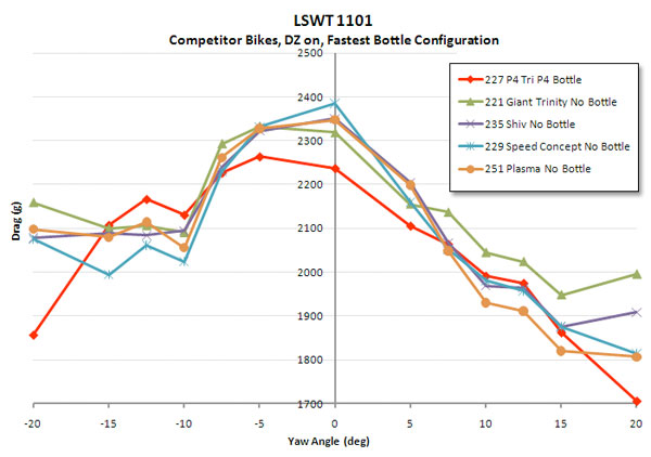
Image source: Slowtwitch, http://www.slowtwitch.com/Tech/Cervelo_P4_in_the_Tunnel_1929.html

Looking at the chart, it is quite obvious that under wind angles of -5° to +5°, the Scott Plasma 3 is not the most aerodynamic bike in this test. However, things change in wind angles of -15° to -7.5° and 7.5° to 15°. Under these conditions, the Scott Plasma 3 is either the best bike (non-drive side) or the second best (drive side). And according to an exhaustive analysis of Trek (Speed Concept White Paper, Page 11), effective wind angles of 7.5° to 12.5° occur most often in real life for riding speeds between 29 and 40 km/h.

Overall, the Scott Plasma 3 seems to be the best compromise between top-notch aerodynamic performance and mechanical ease to maintain and to travel with.

Built-Up:

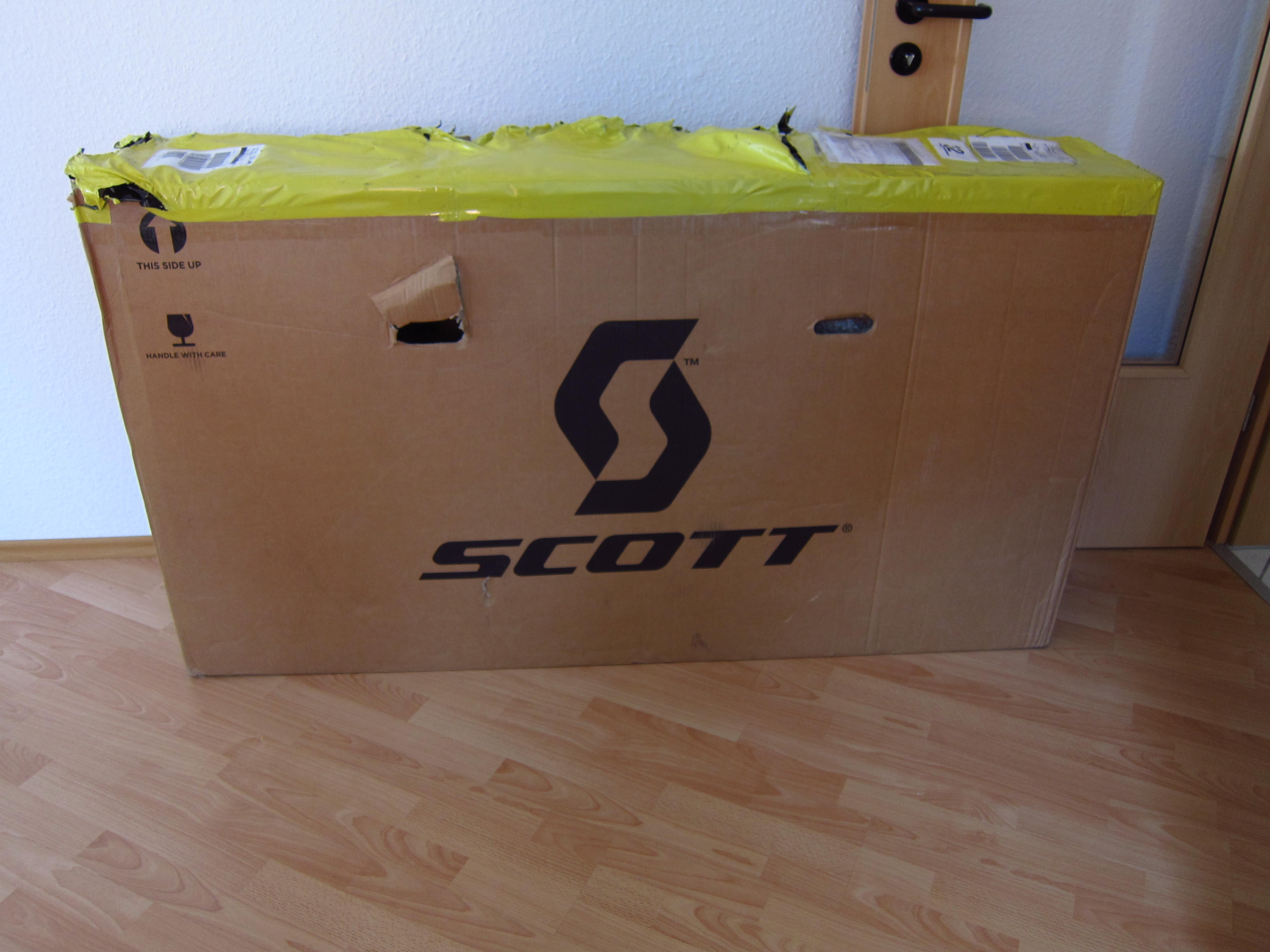
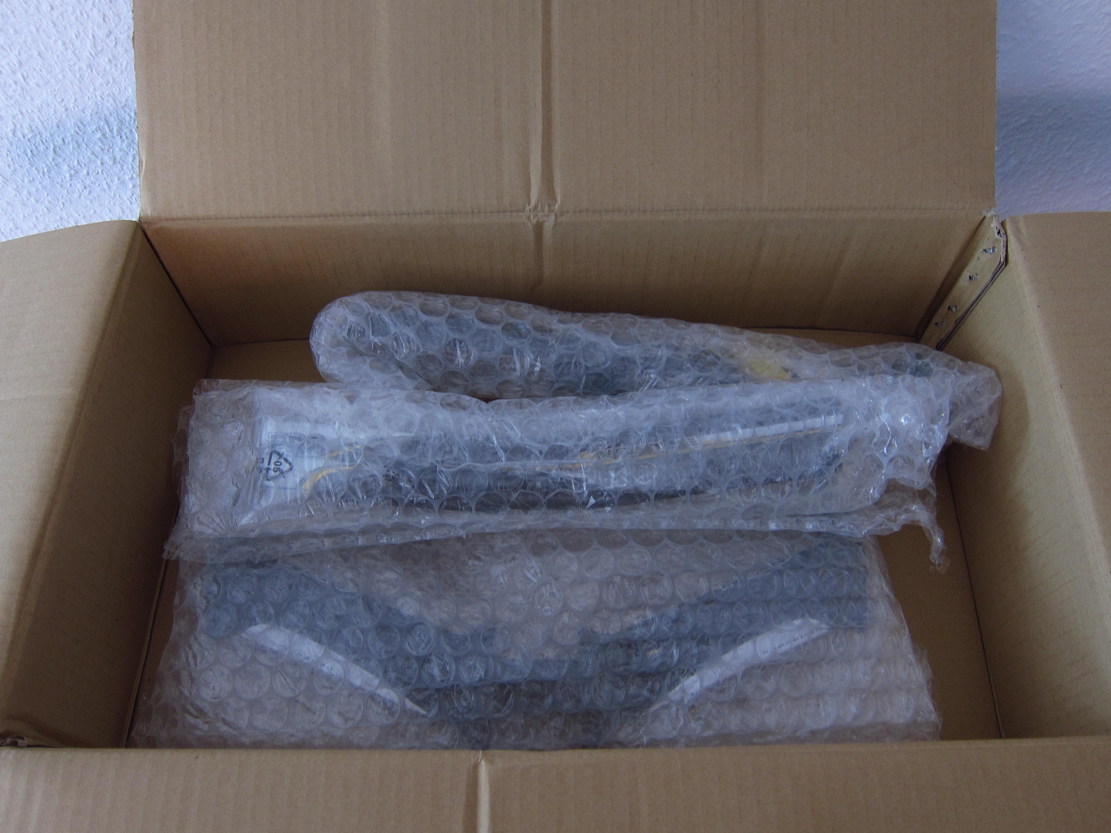
I decided to built up the bike by myself, so I ordered a frameset only. Finally, mid of September, the magic box arrived 😉

20131024_Scott-Plasma-TT_01

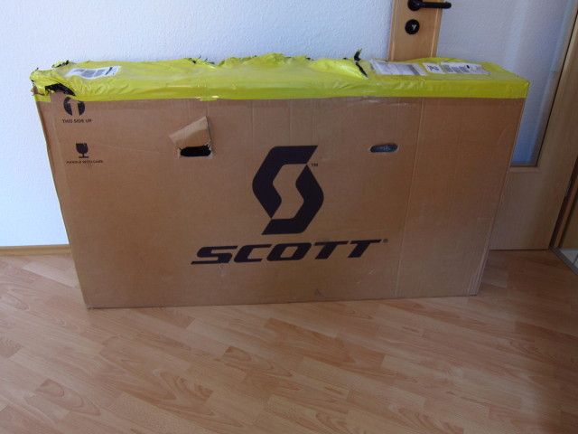
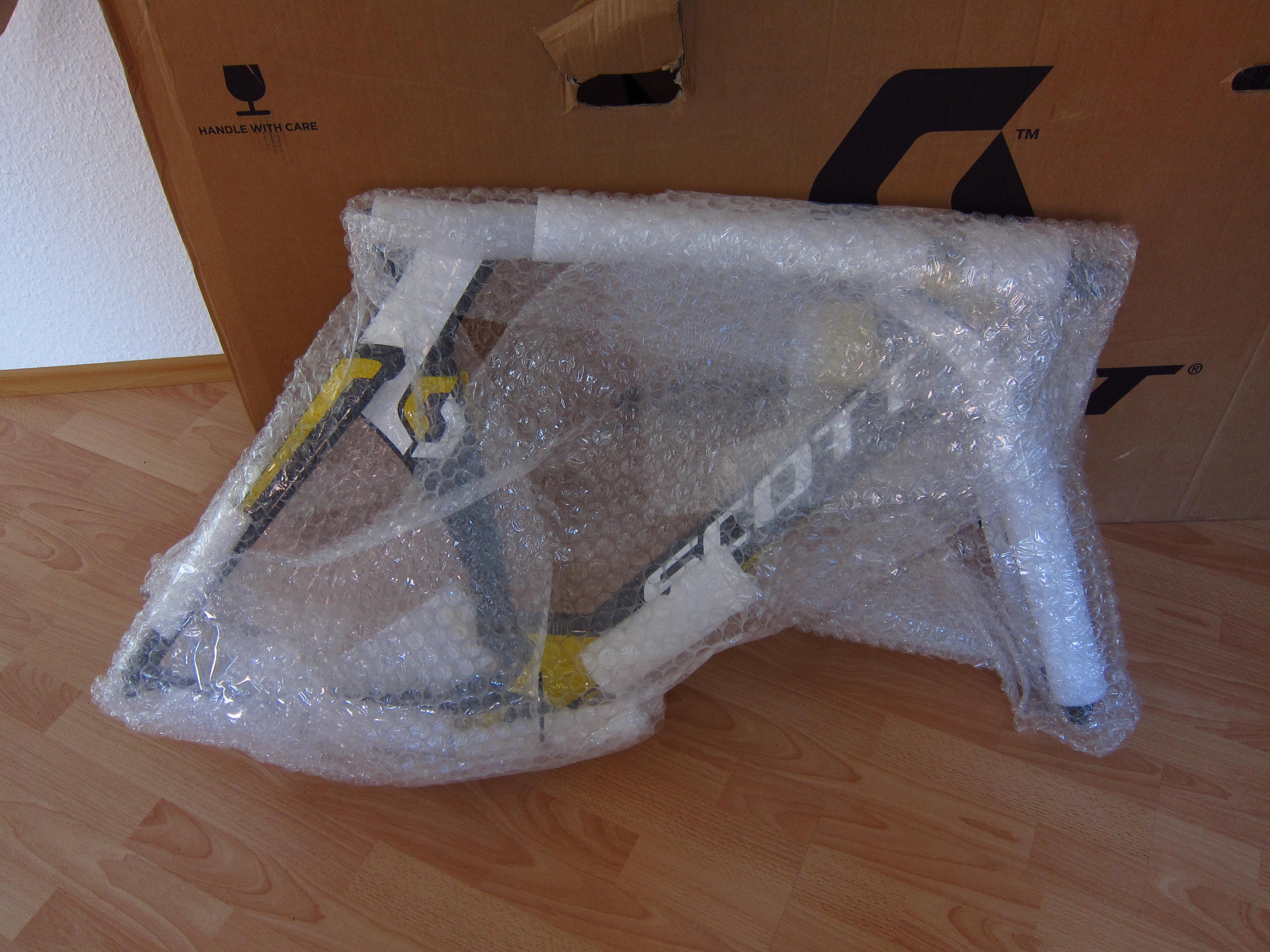
It was really hard to take pictures whilst unboxing – yet I wanted to document what’s in the box.

20131024_Scott-Plasma-TT_02

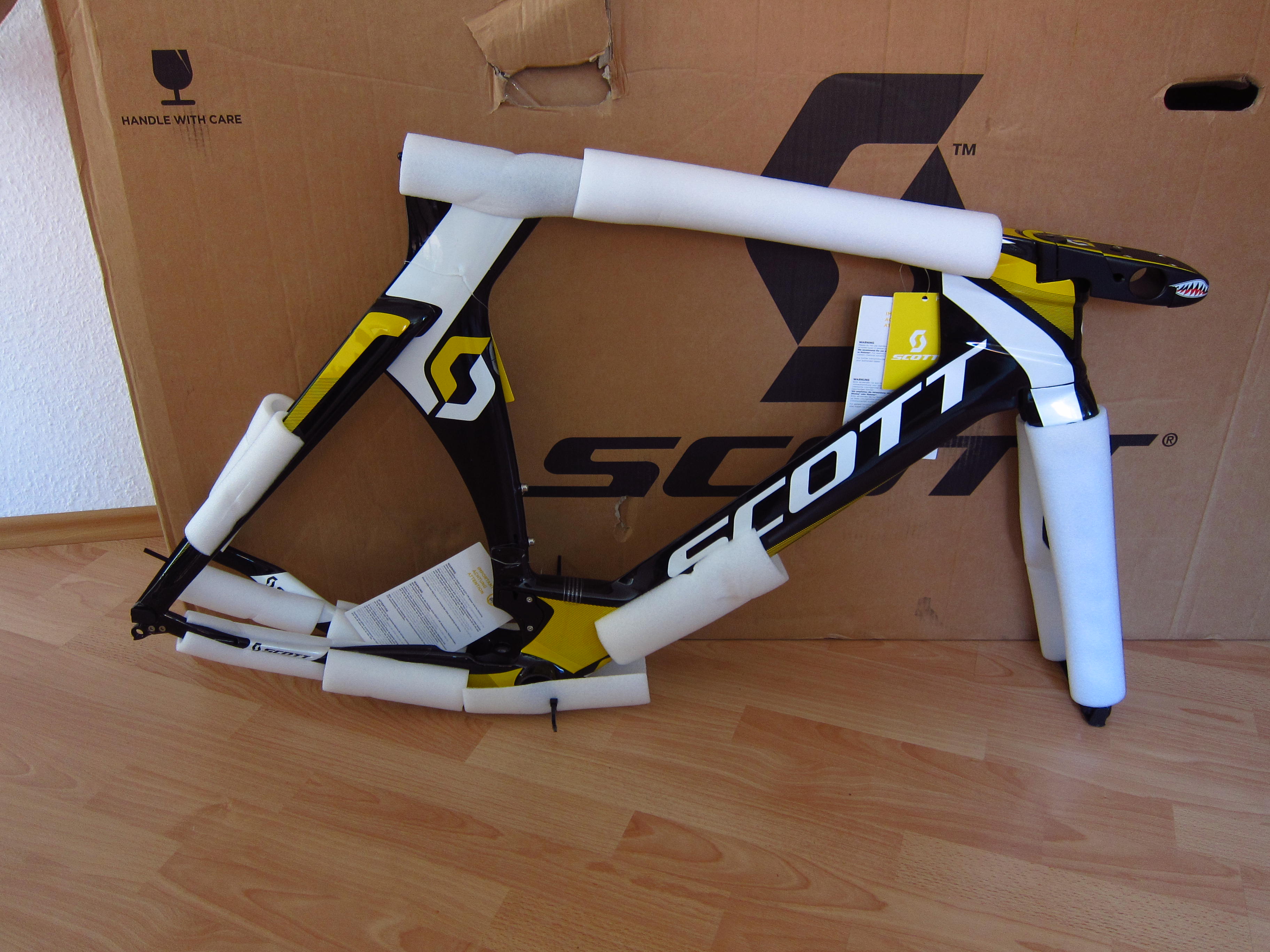
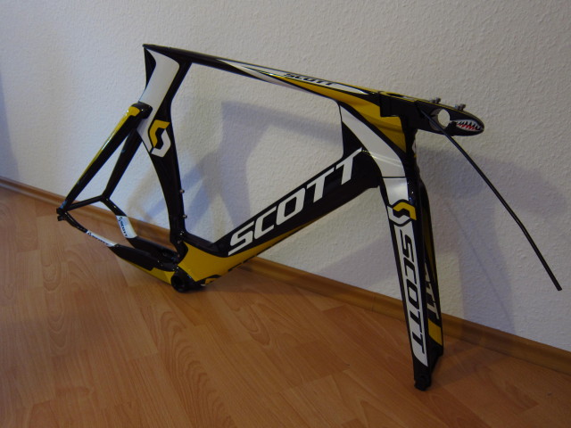
The frame was properly packed to avoid dings or scratches.

20131024_Scott-Plasma-TT_03

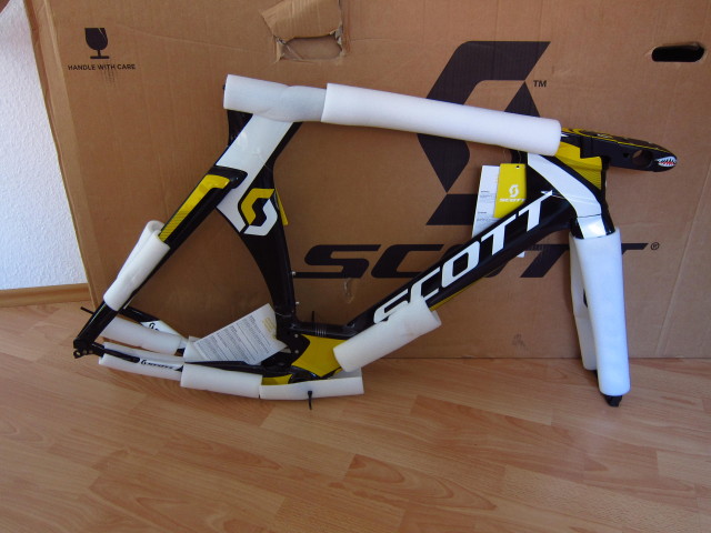
It already looks fast, even without wheels attached ;-).

20131024_Scott-Plasma-TT_04

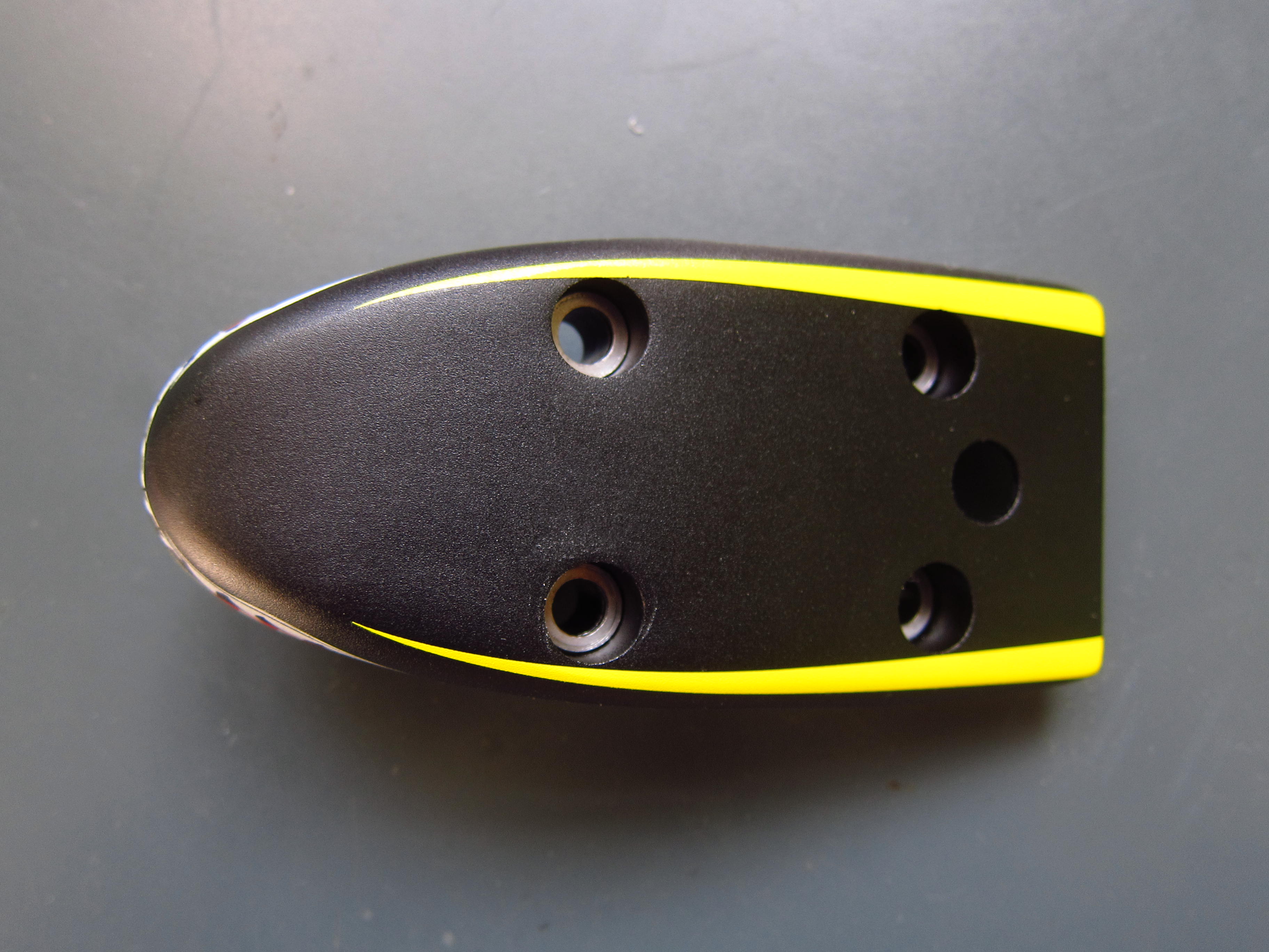
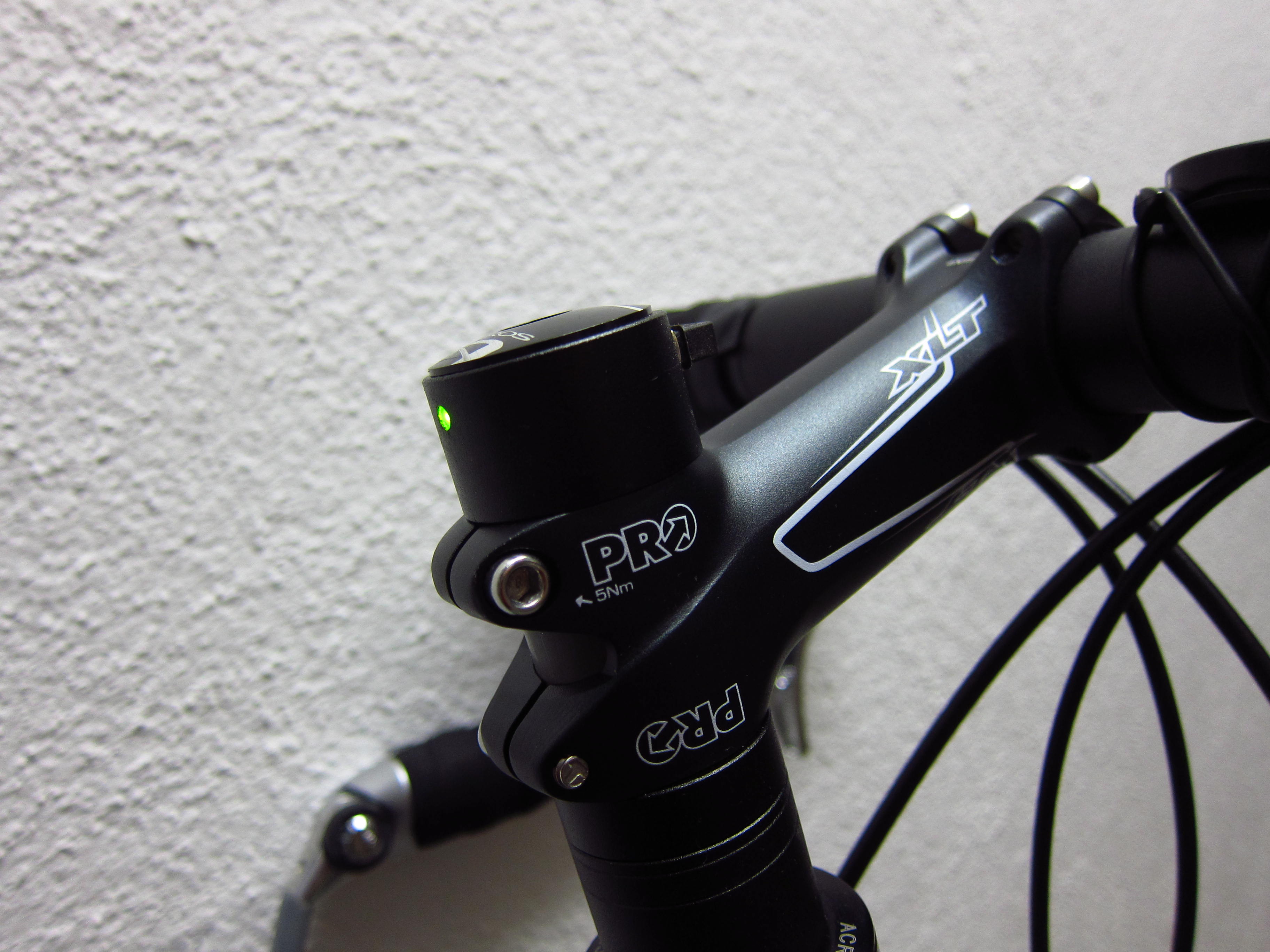
There are two different options of the Scott Plasma 3: The “Premium” version is designed for mechanical shifting and features a rising stem. The “TT” version is designed for electronic shifting with internal cable routing through the flat stem. I decided to go for the latter. Basically, the Scott Plasma TT is still one of the very few superbikes which allow hidden cable routing at the front. And the stem graphics are quite attractive as well.

20131024_Scott-Plasma-TT_05

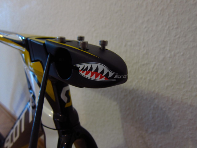
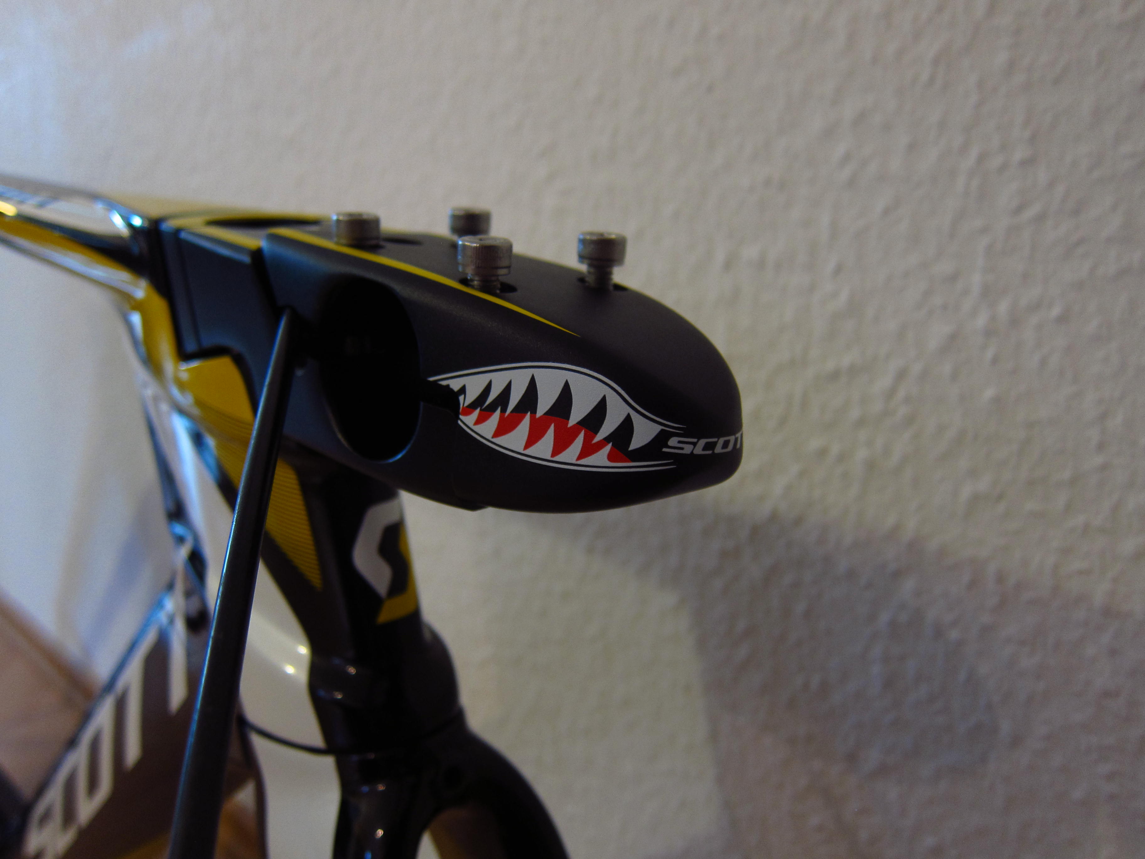
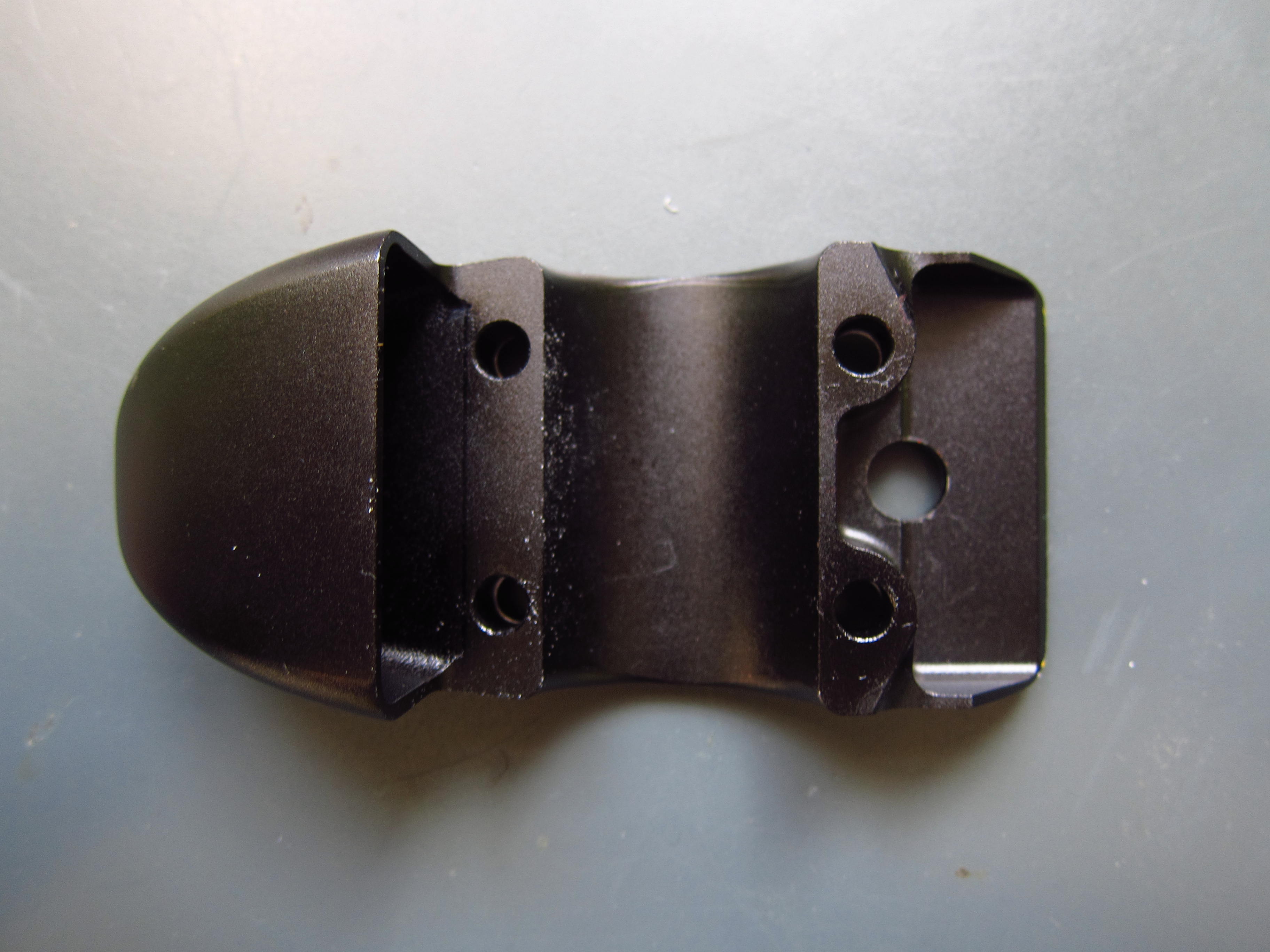
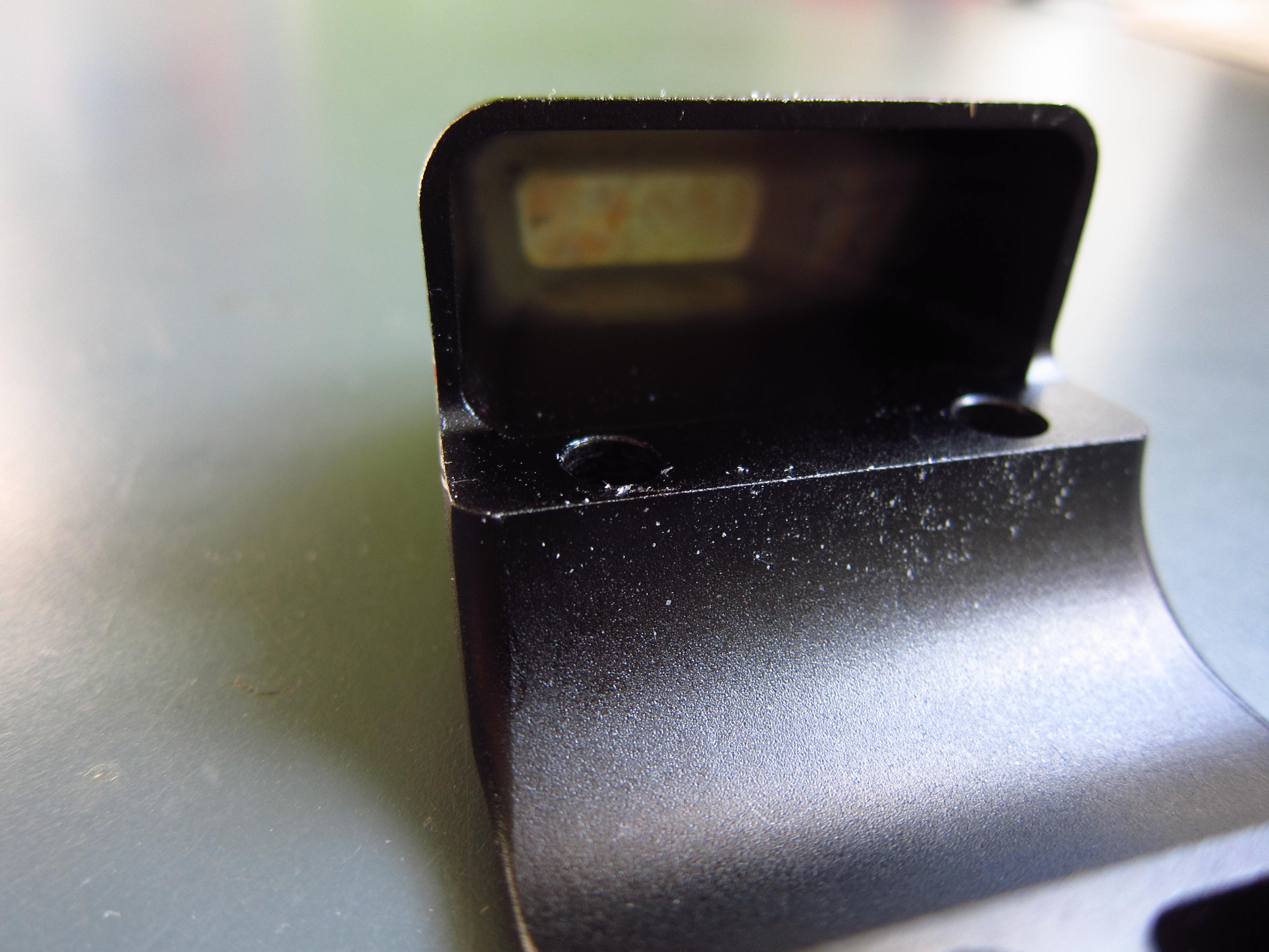
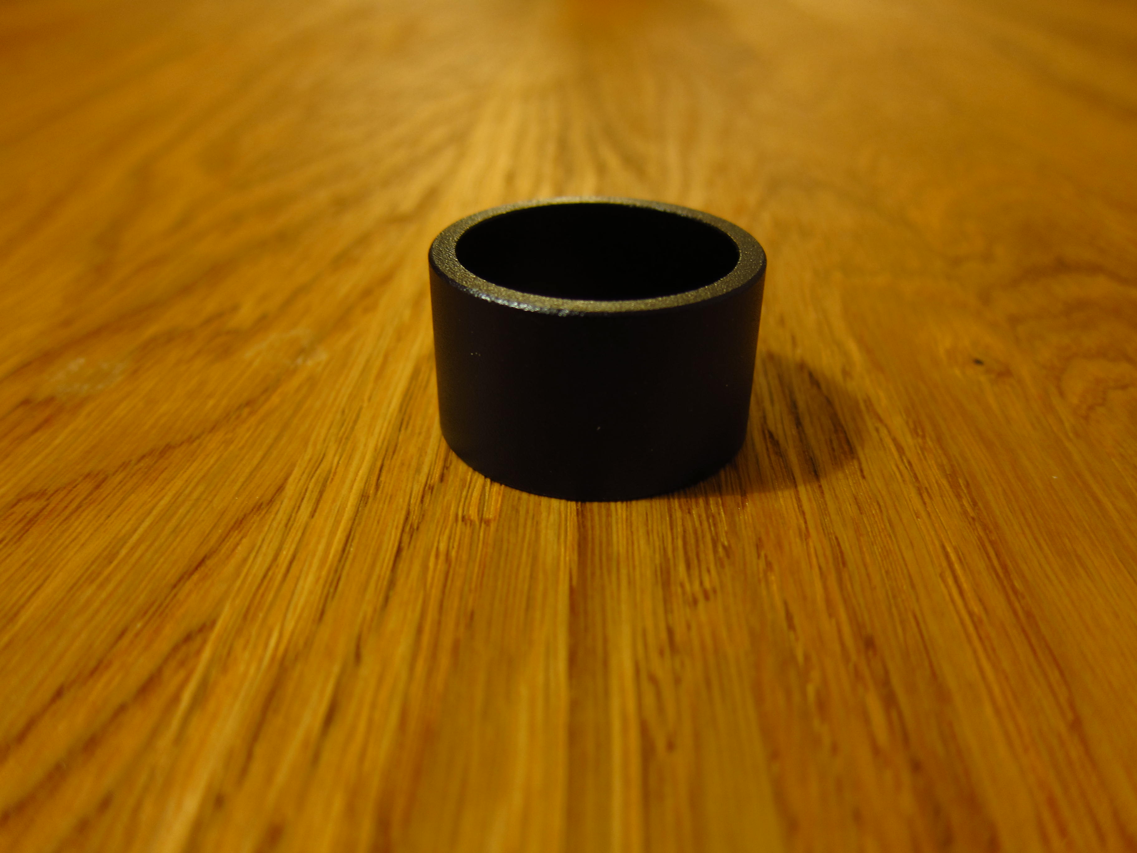
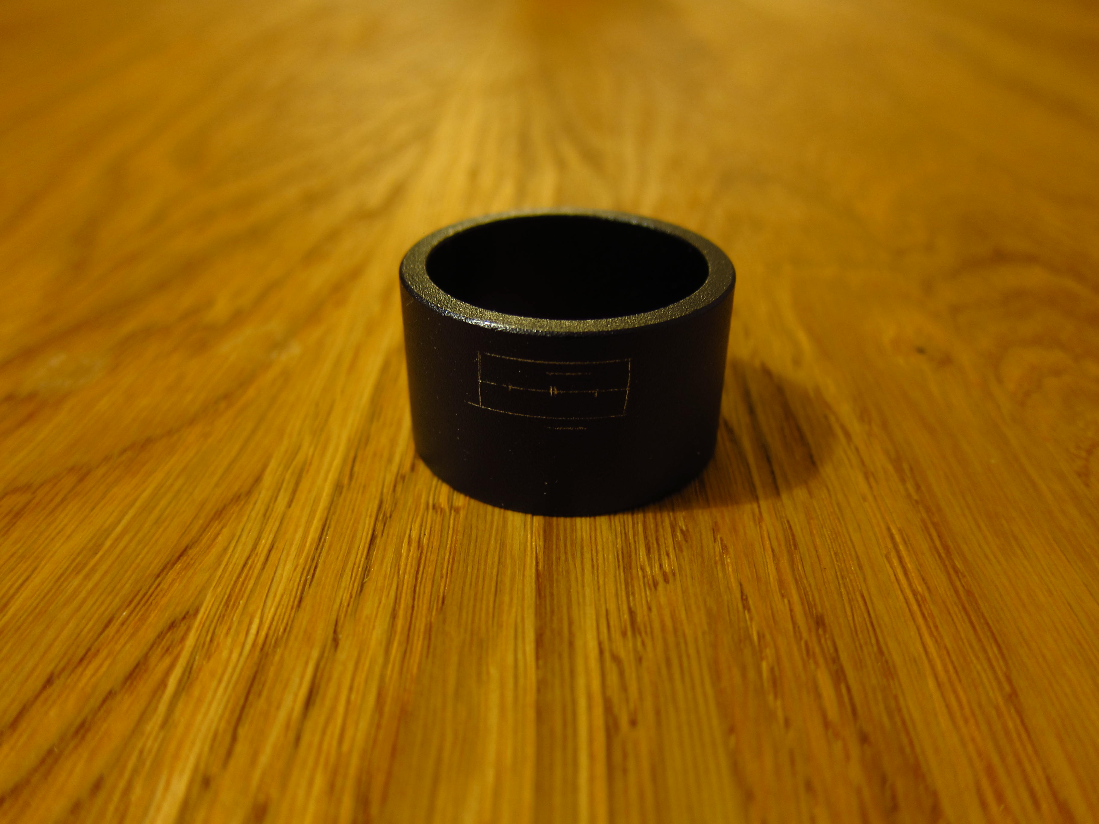
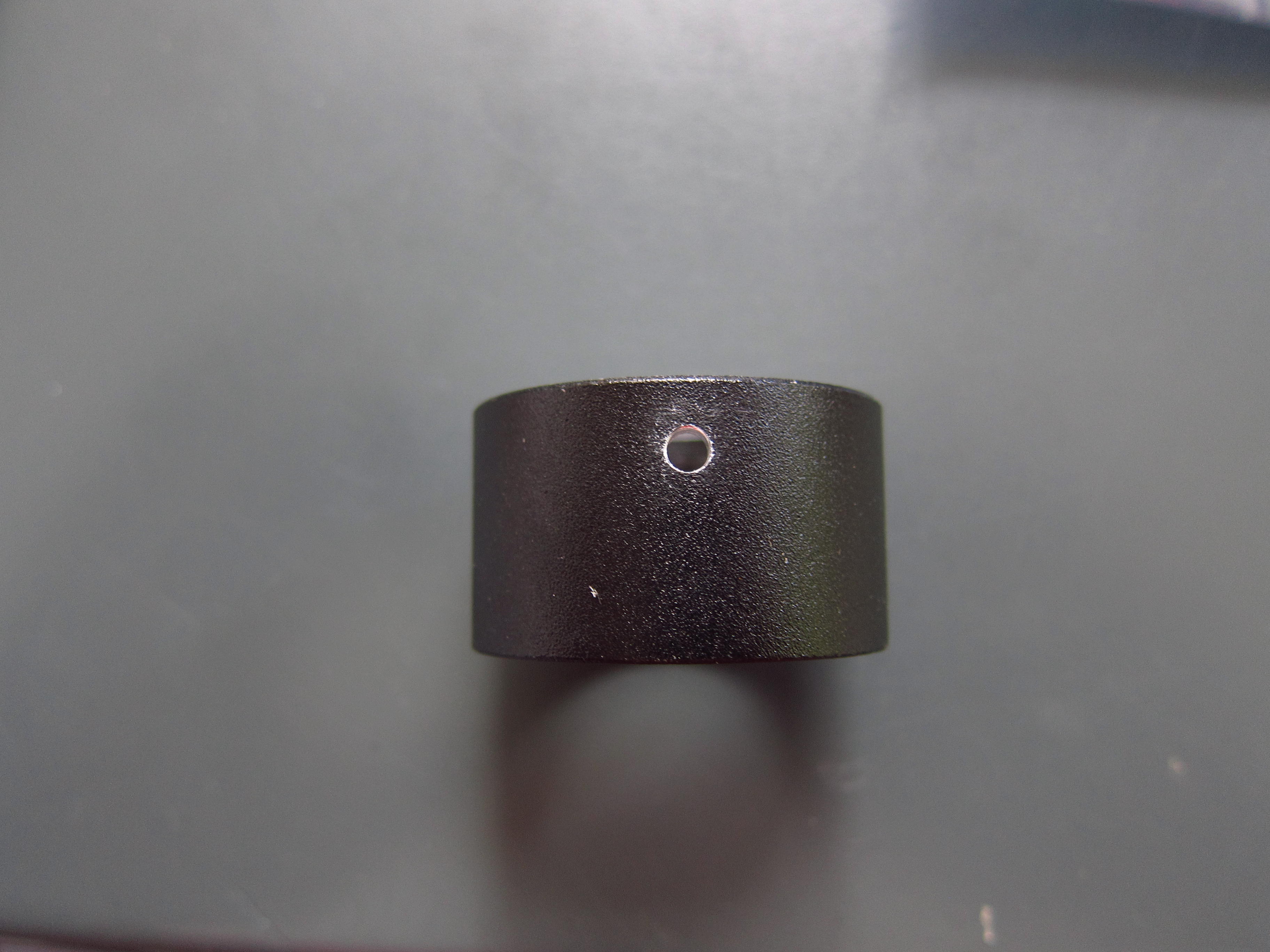
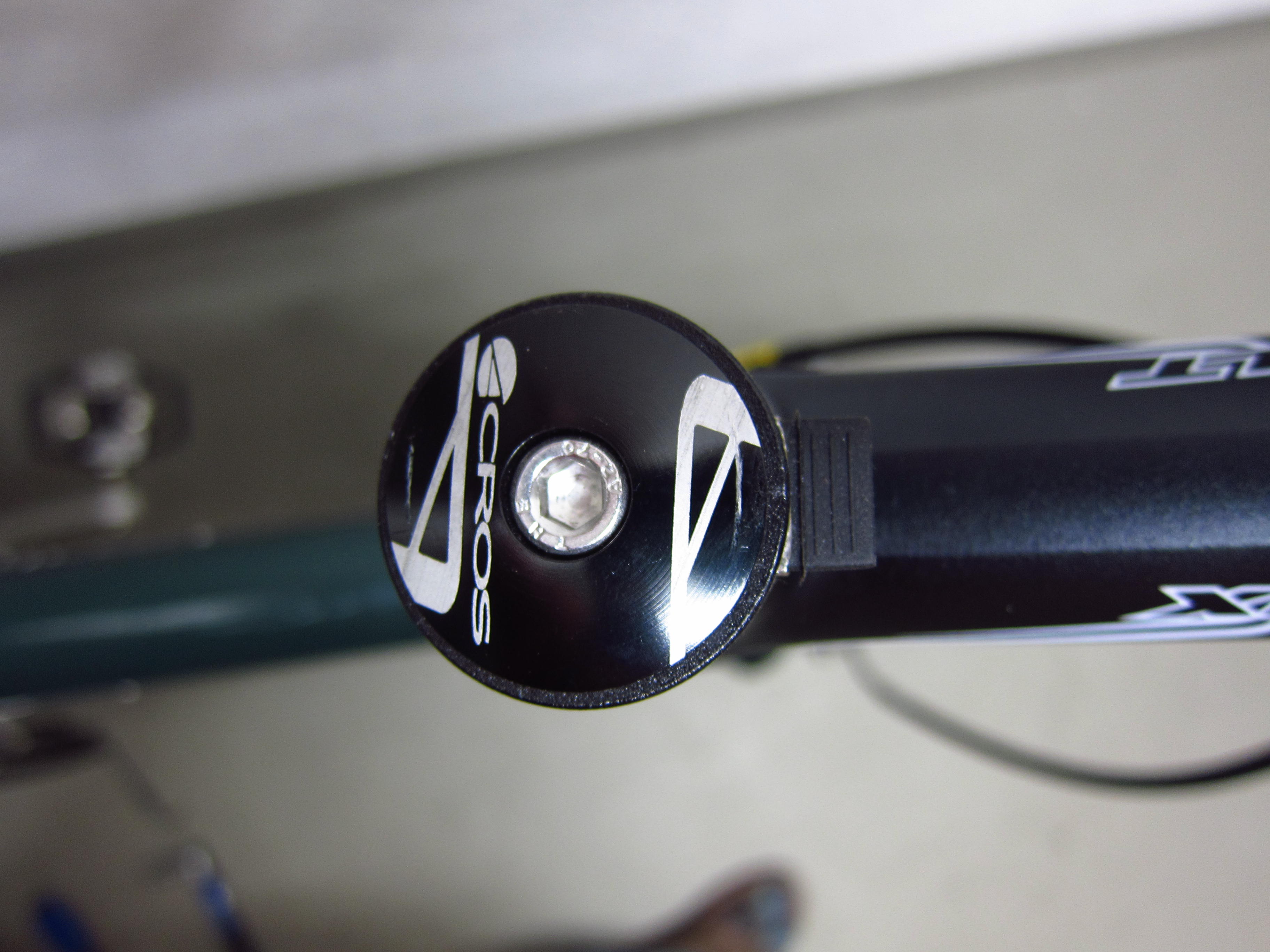
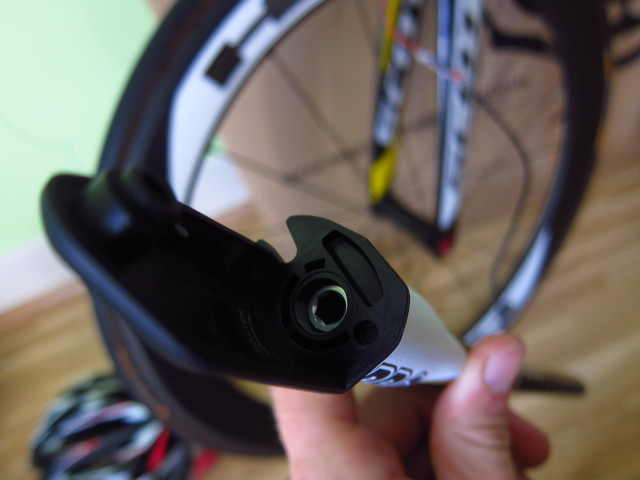
The top cap of the stem is fastened by four bolts…

20131024_Scott-Plasma-TT_06

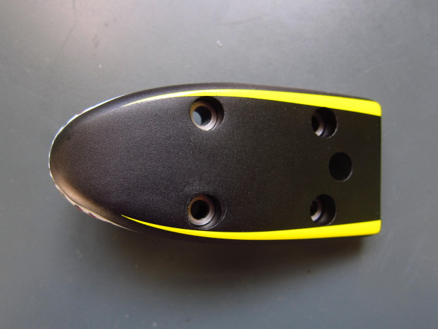
…and milled out from the inside. Nevertheless, the complete stem weighs a rather hefty 451g.

20131024_Scott-Plasma-TT_07

20131024_Scott-Plasma-TT_08

Other than that, the box includes other components,

20131024_Scott-Plasma-TT_09

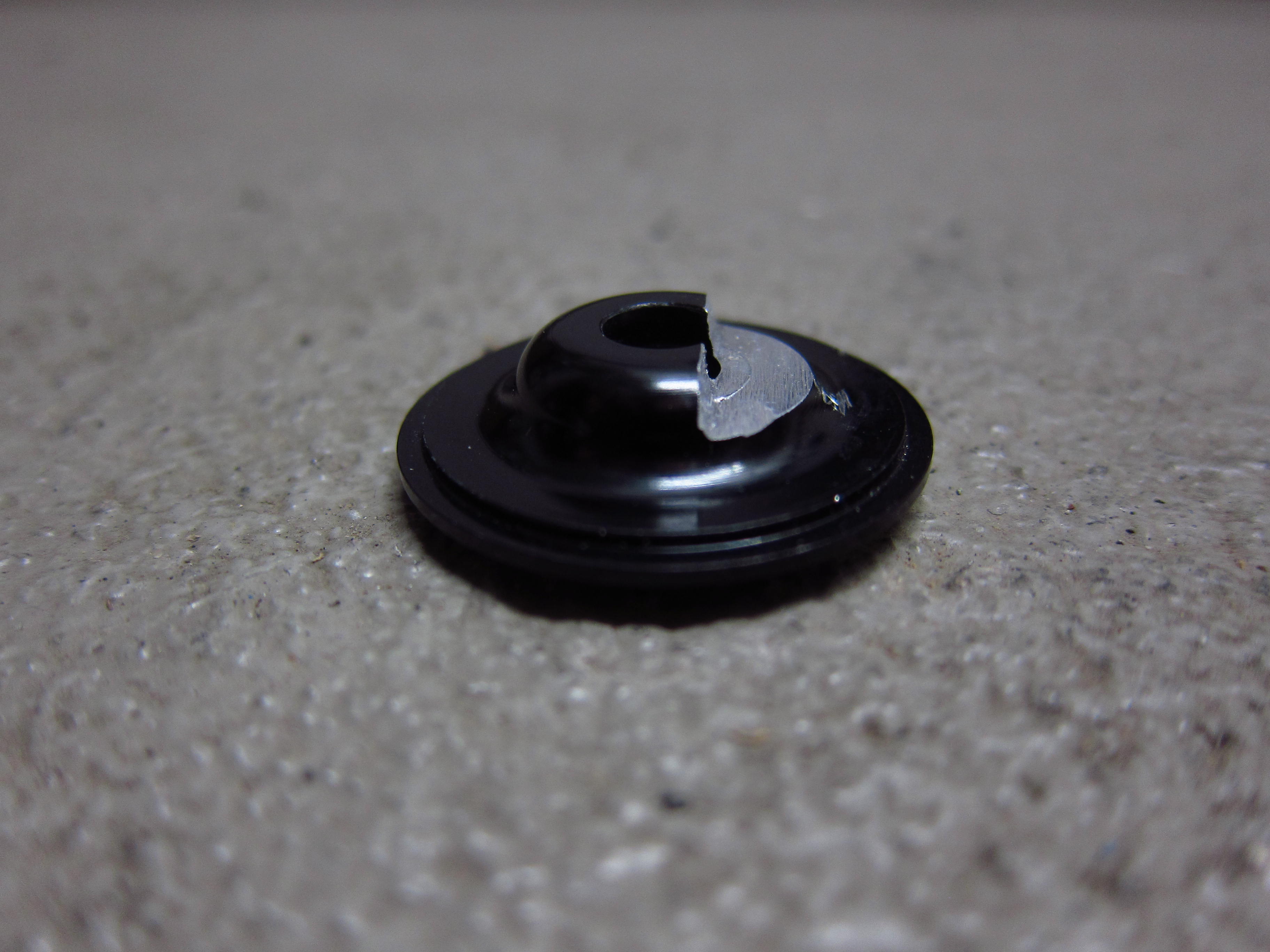
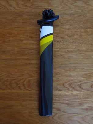
a seatpost which needs to be cut to the appropriate length,…

20131024_Scott-Plasma-TT_10

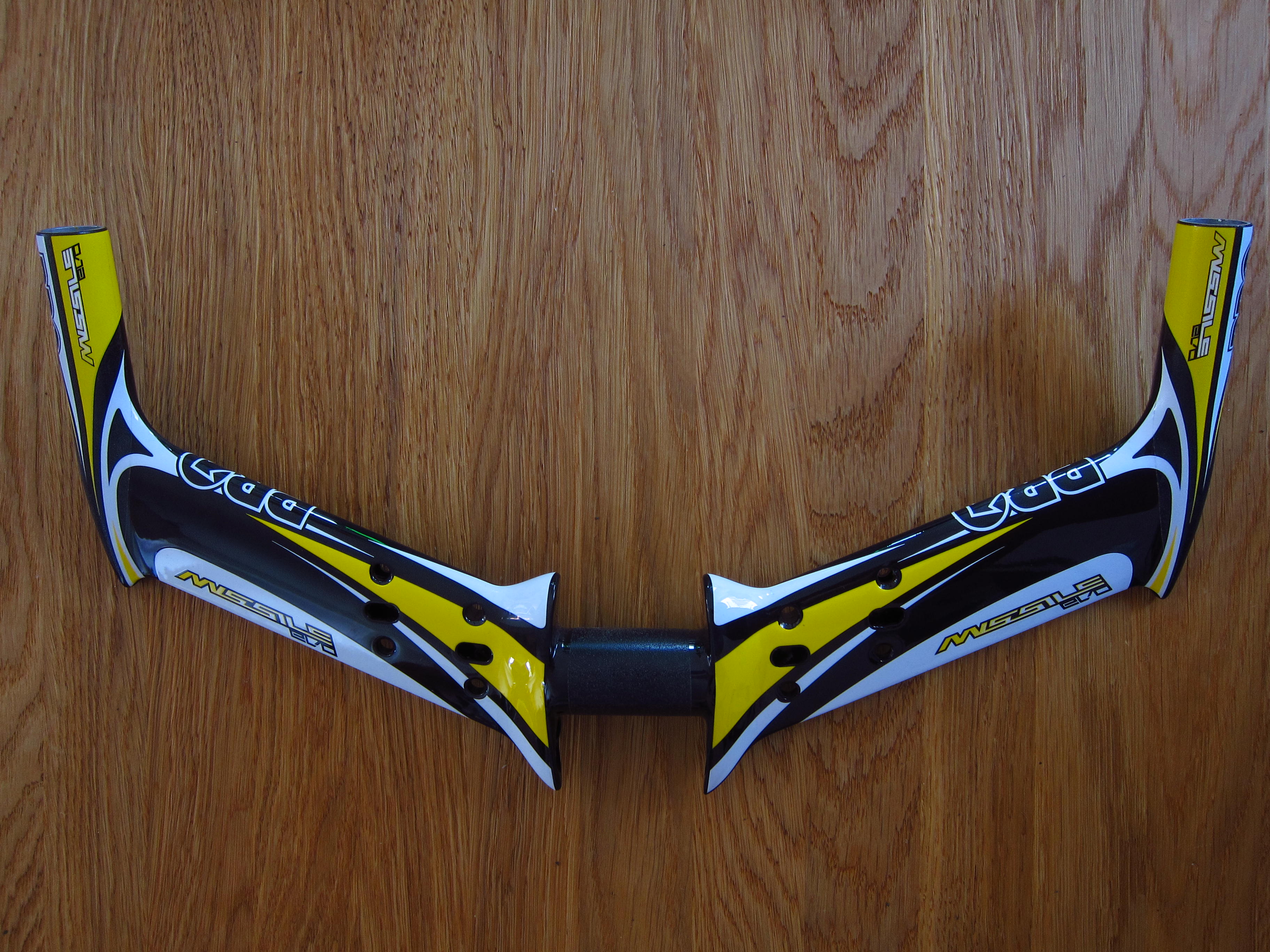
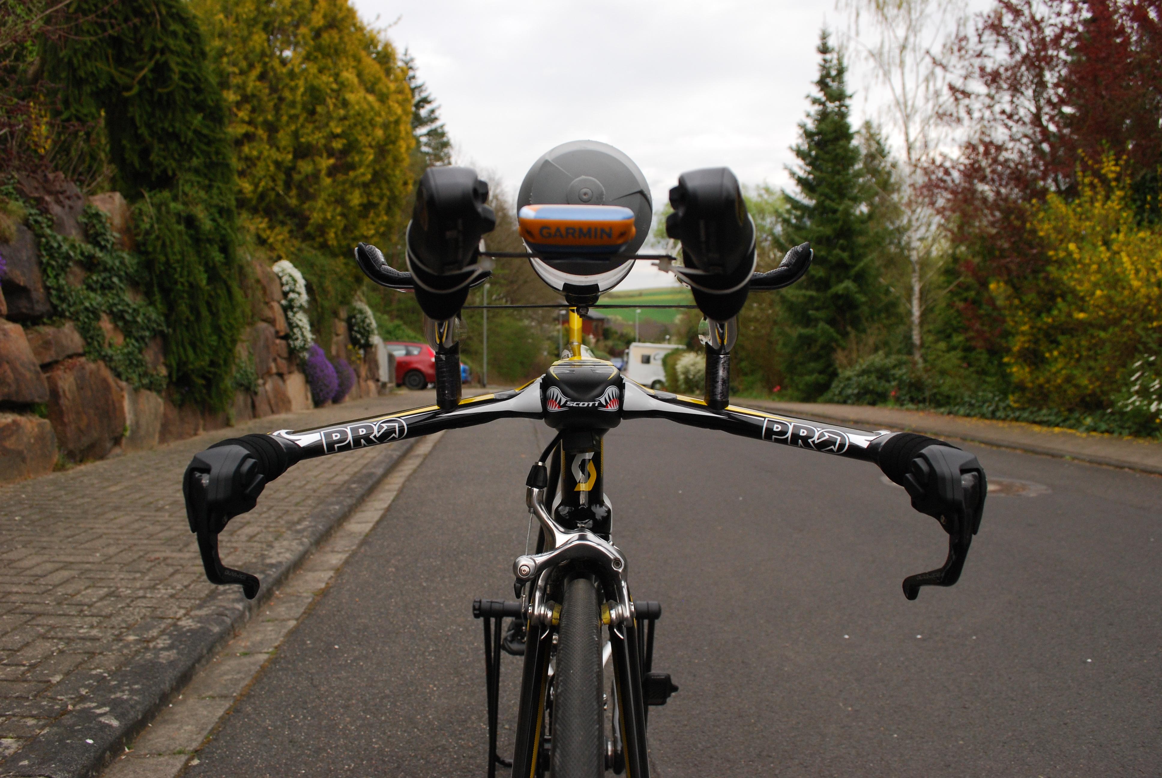
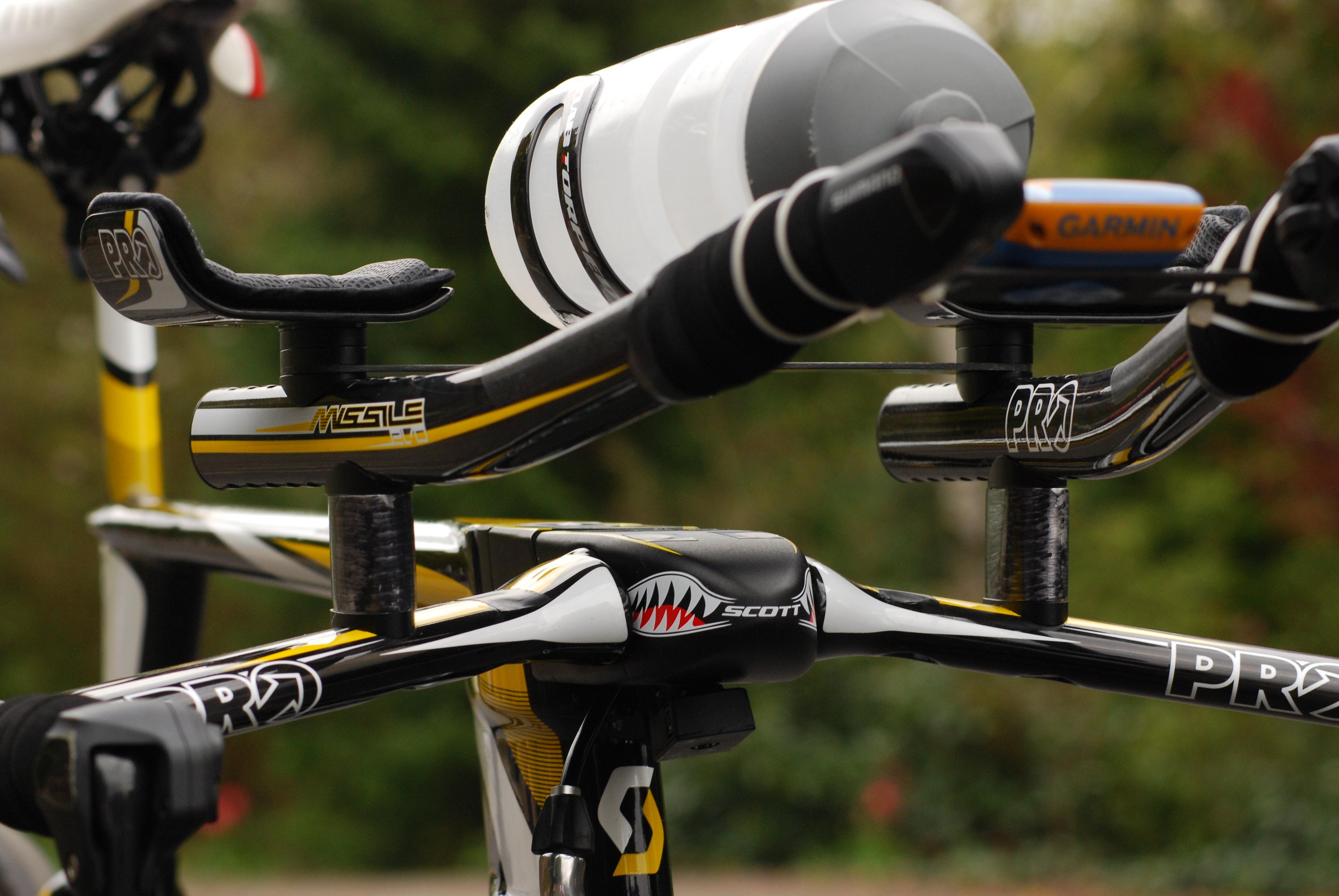
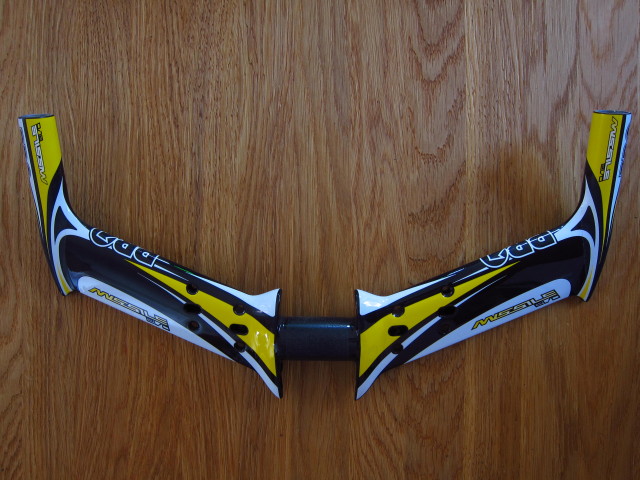
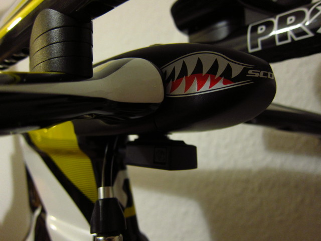
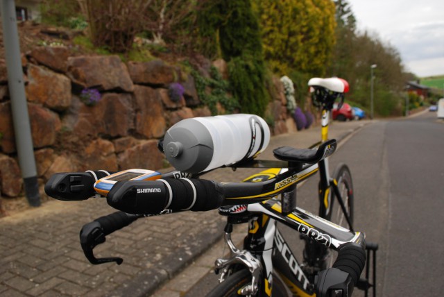
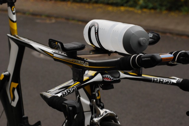
a Pro Missile Evo Basebar,…

20131024_Scott-Plasma-TT_11

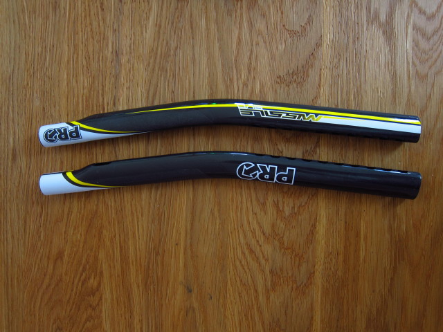
Pro Missile Evo Extensions as well other small items like headset bearings, a cutting tool for the seatpost and an instruction manual.

20131024_Scott-Plasma-TT_12

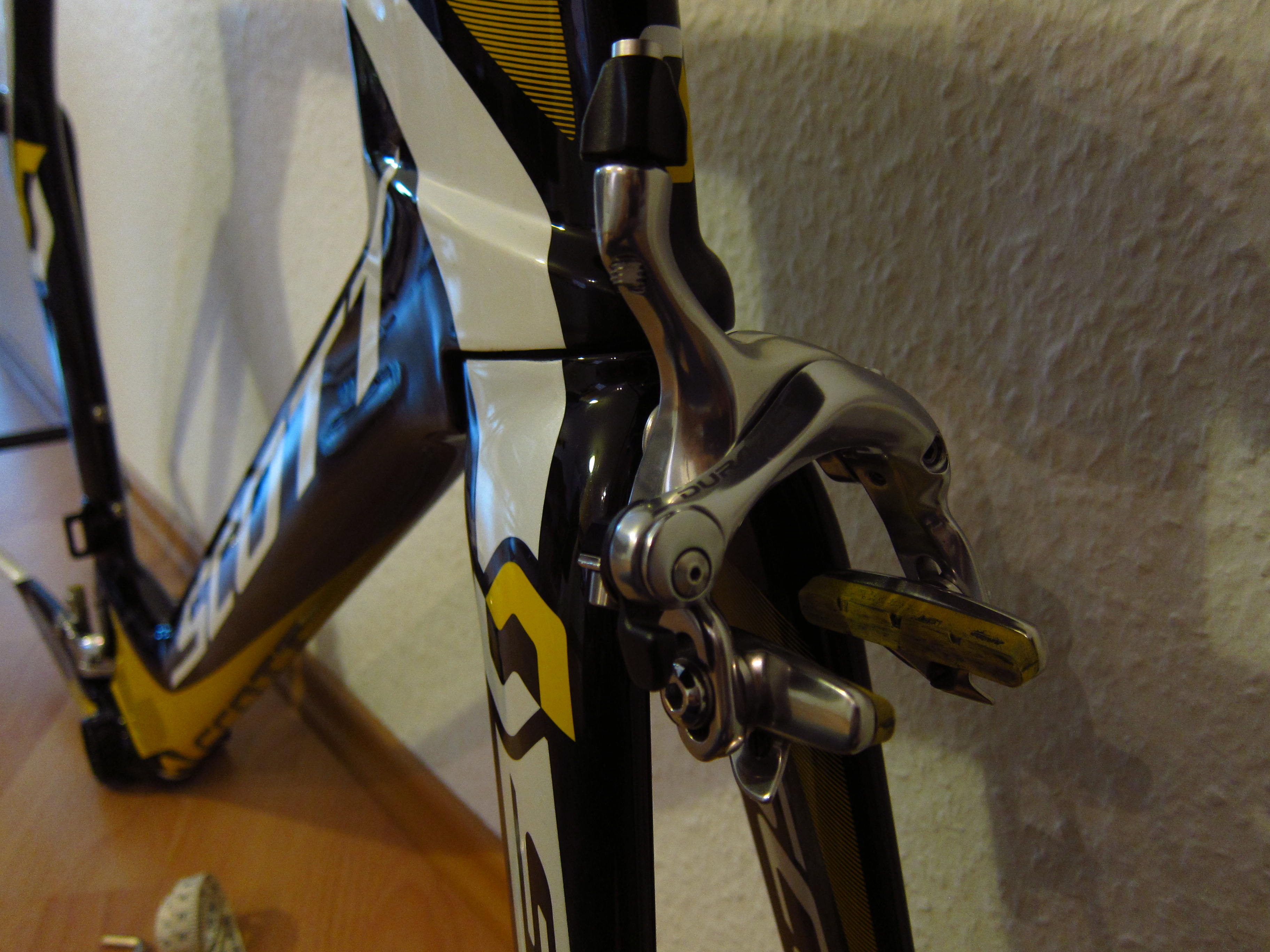
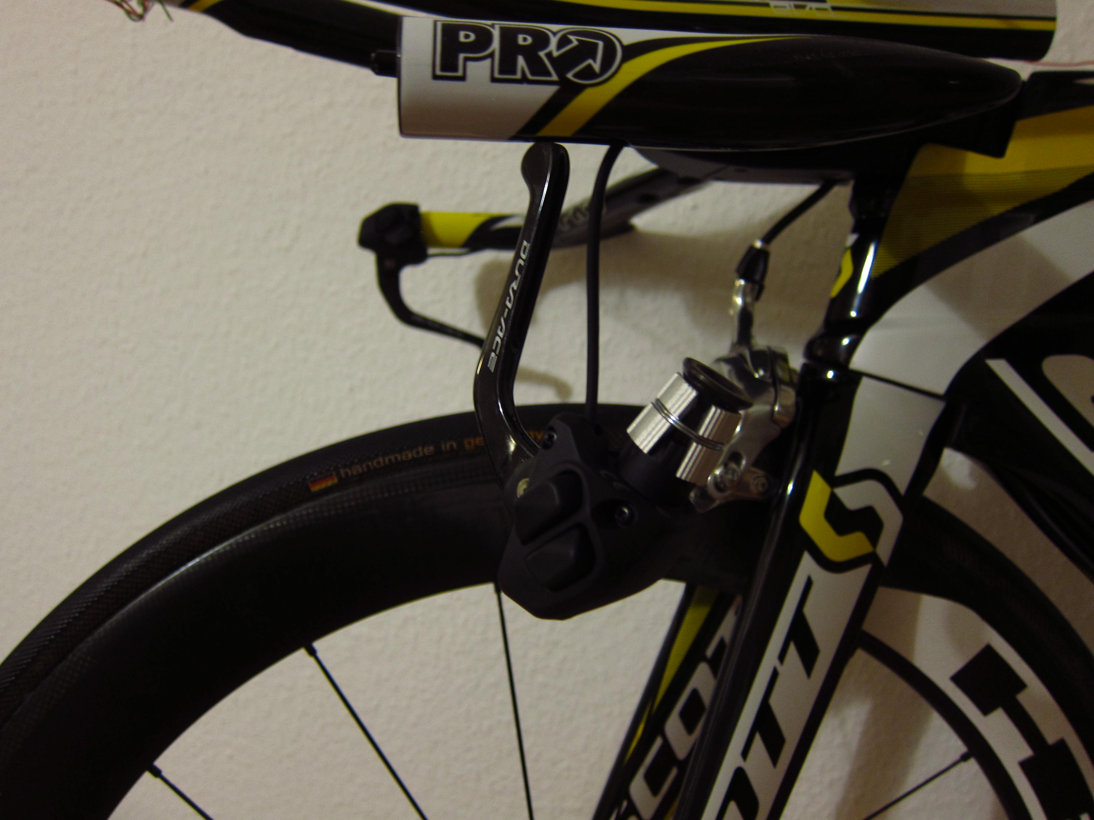
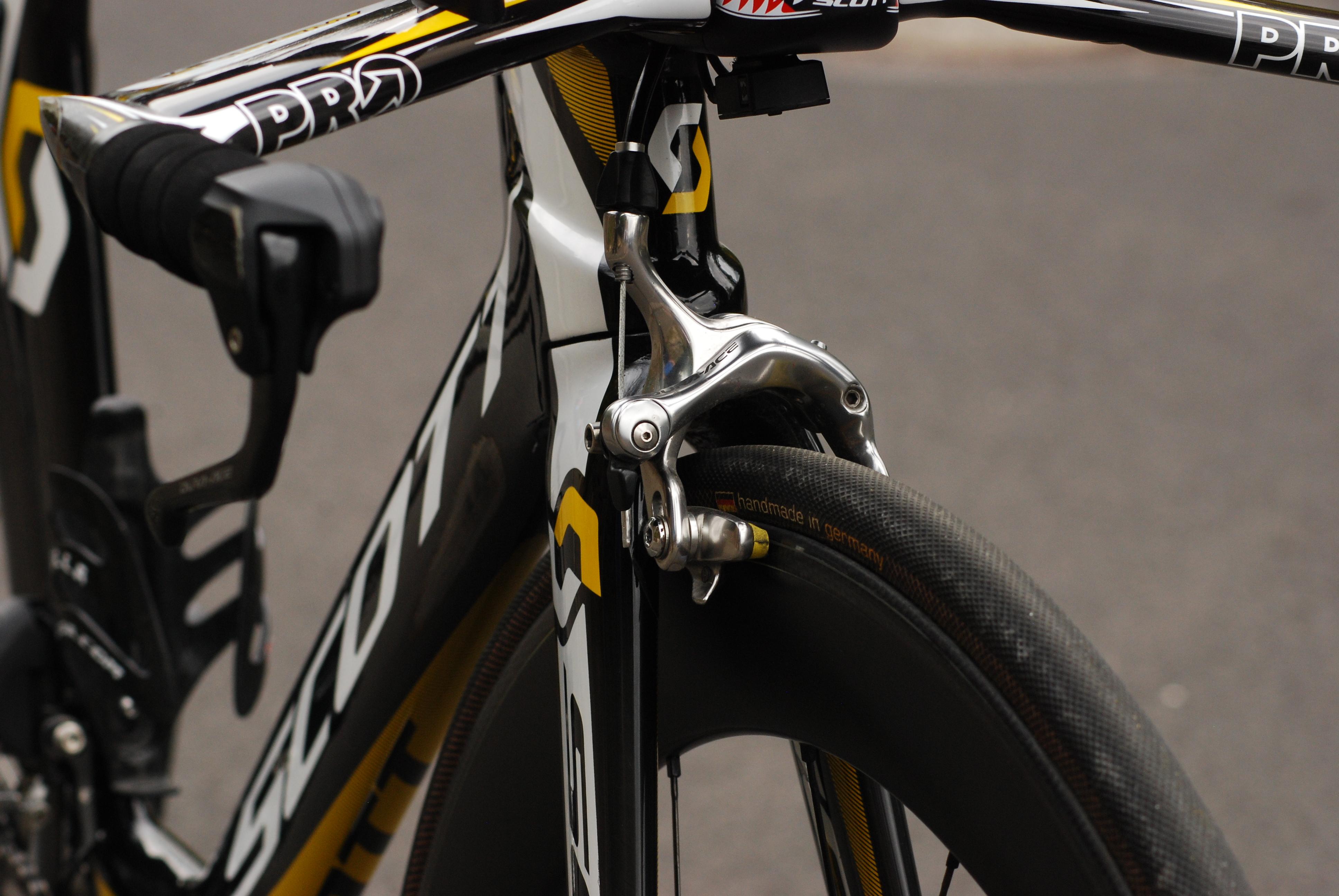
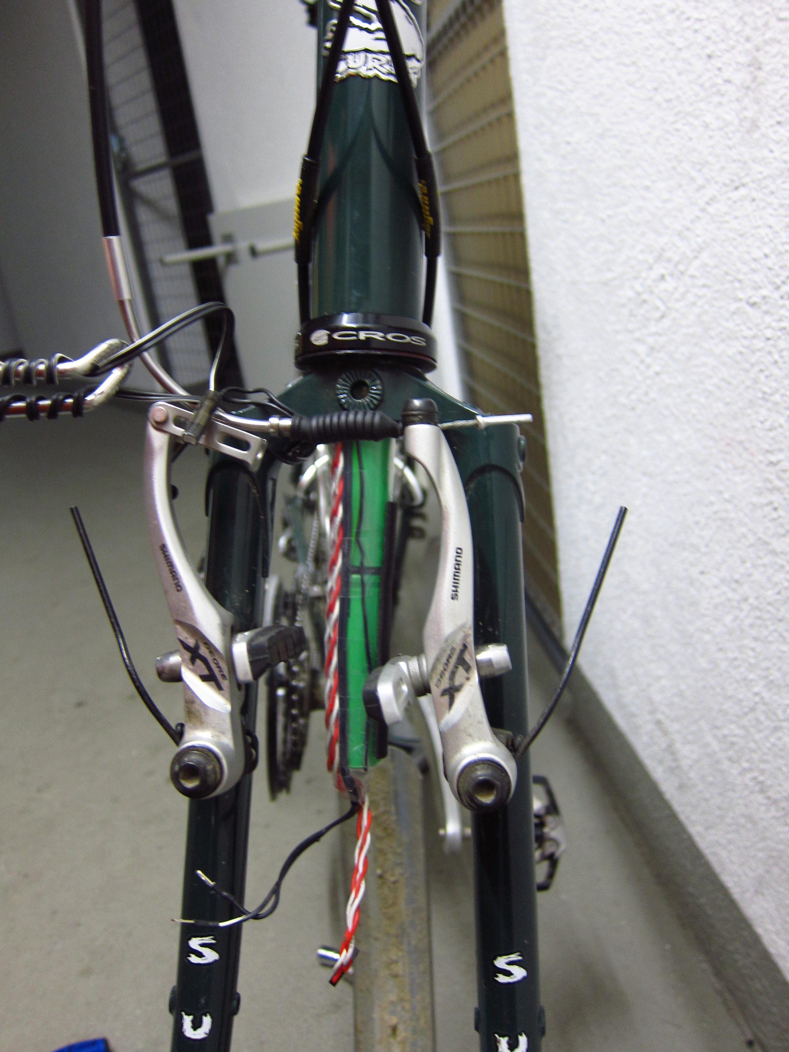
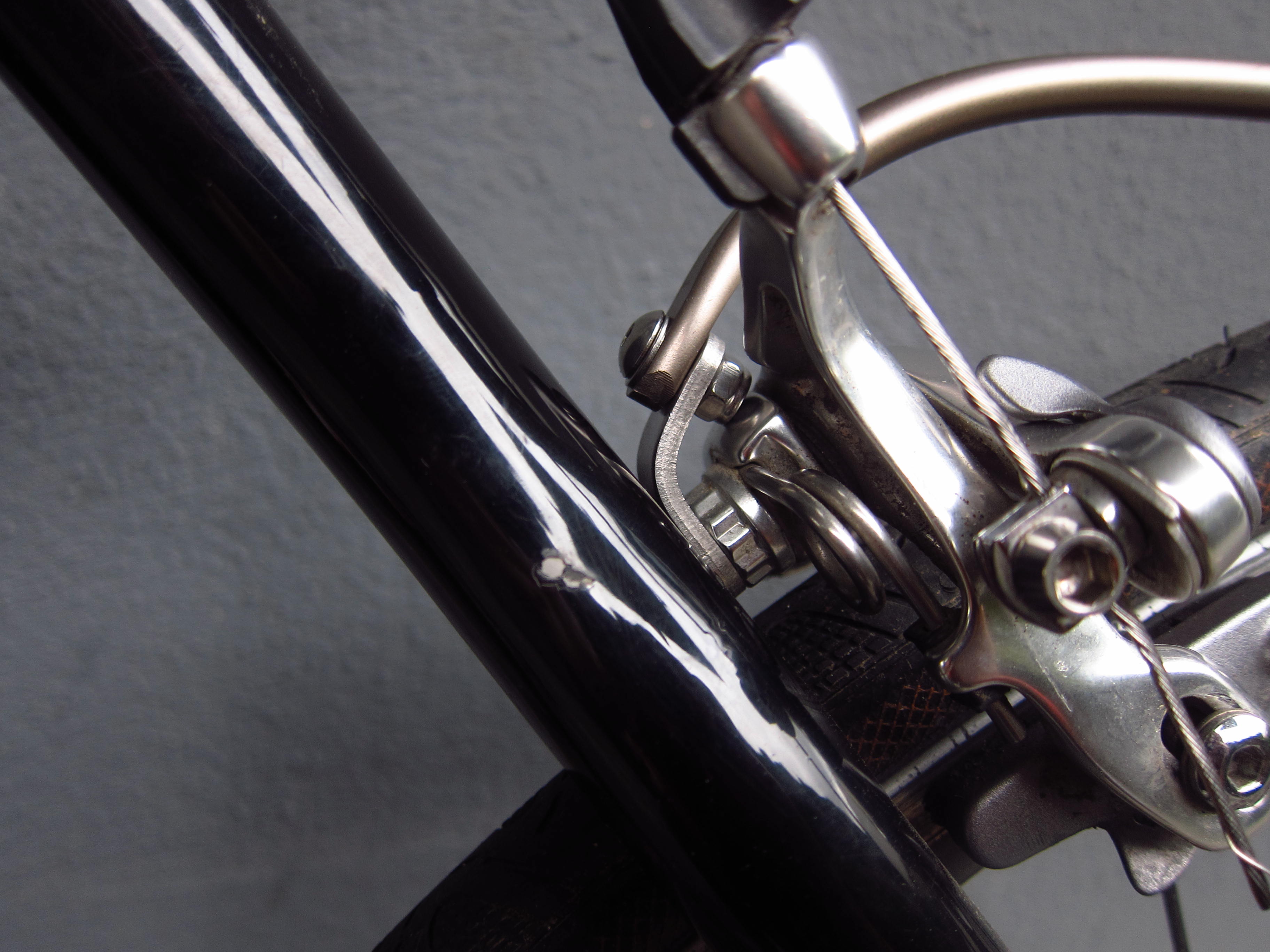
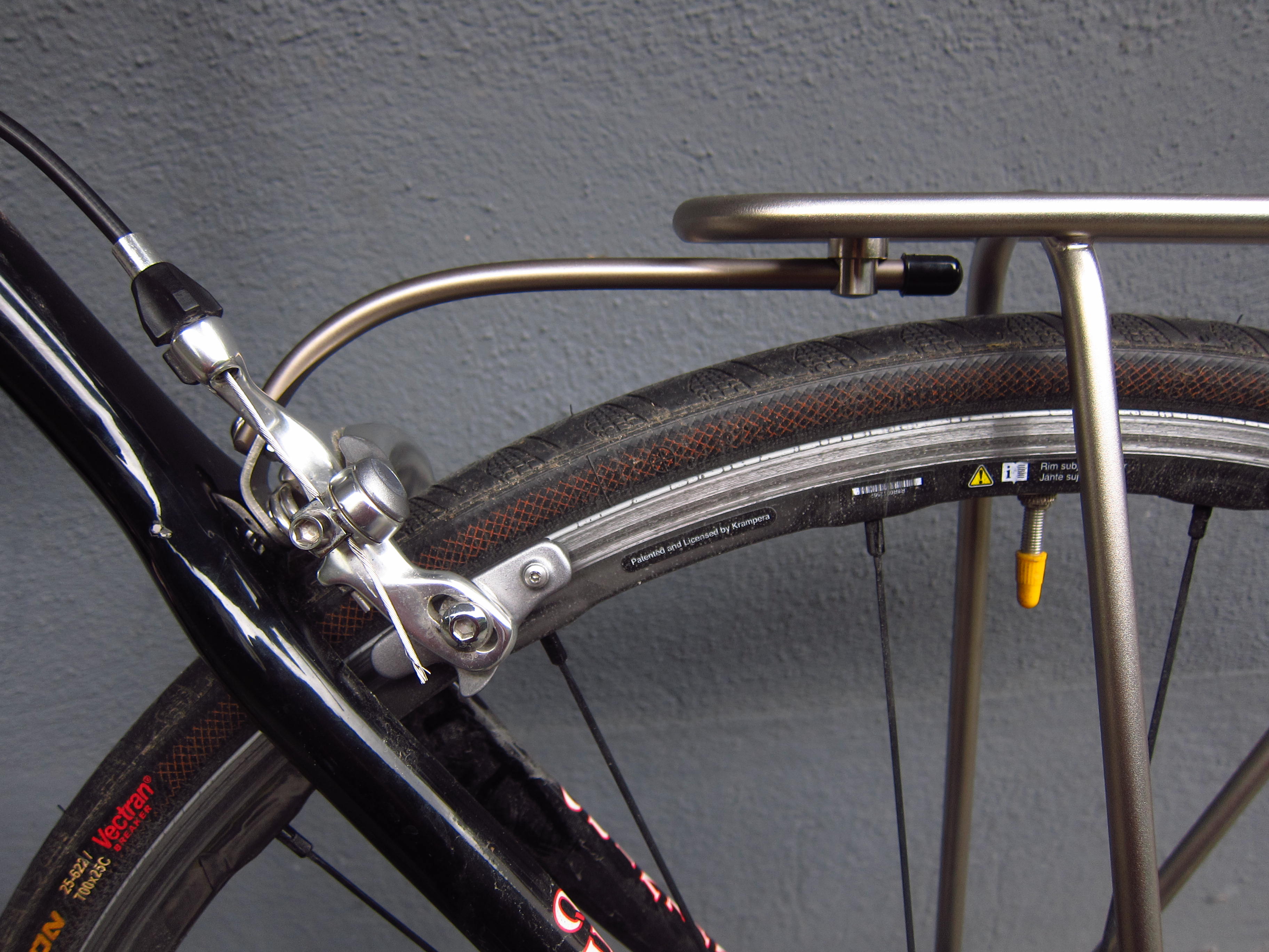
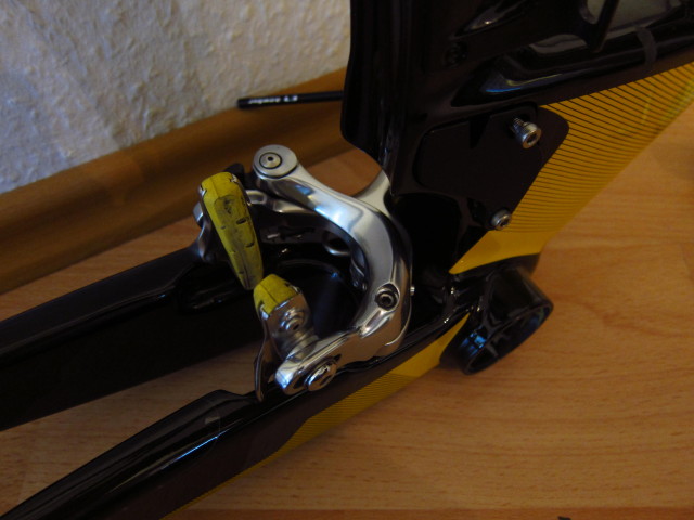
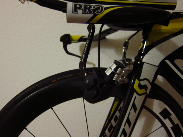
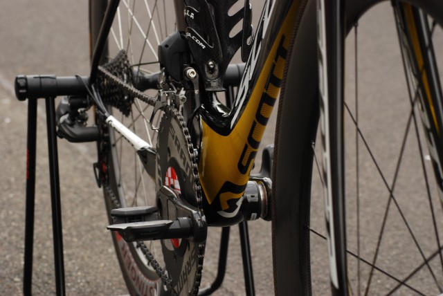
First of all, I started mounting the brakes. While the frame is designed for standard road brakes, …

20131024_Scott-Plasma-TT_13

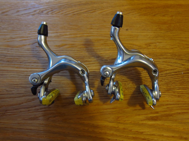
the rear brake must be a Shimano BR-7800 or BR-7900 model to avoid a collision of crank and brake.

20131024_Scott-Plasma-TT_14

Brake installation was quite easy and done in about two minutes. This is really one of the big benefits of this frameset.

20131024_Scott-Plasma-TT_15

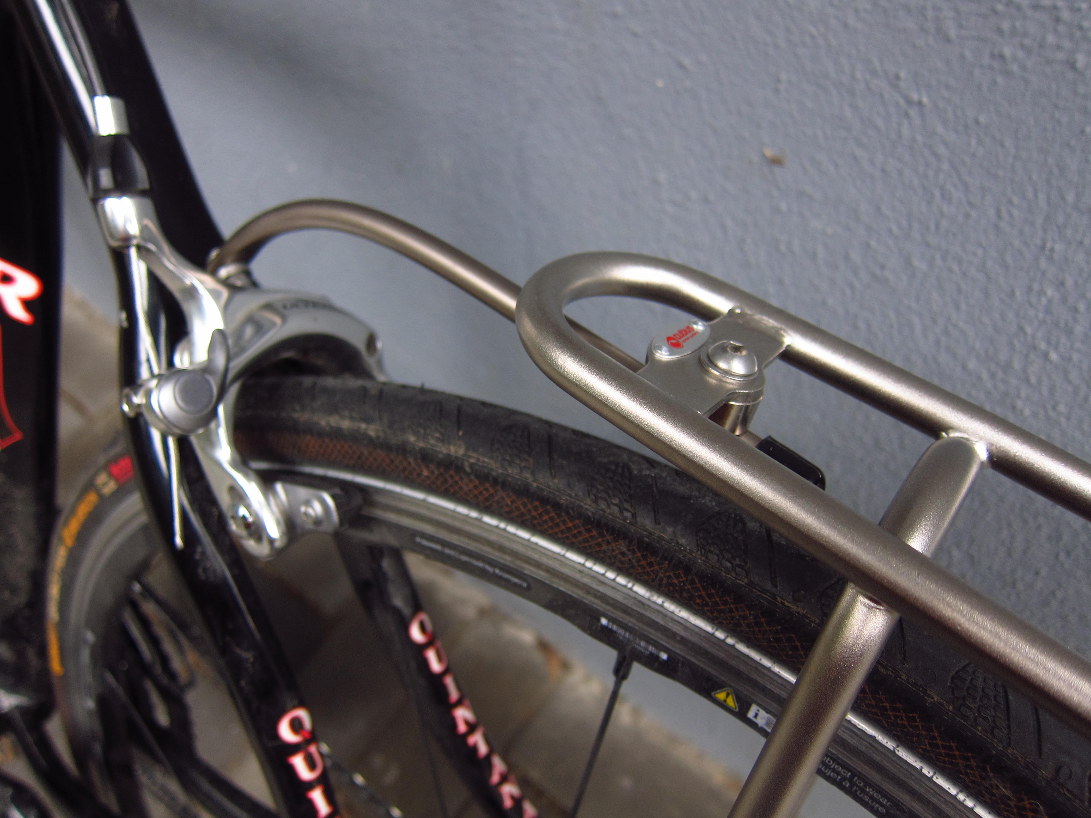
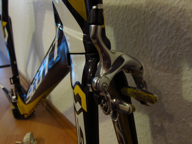
Front brake installation was as easy.

20131024_Scott-Plasma-TT_16

At this stage, I would to give an recommendation regarding the optimal sequence to install the brake and Di2 cables:

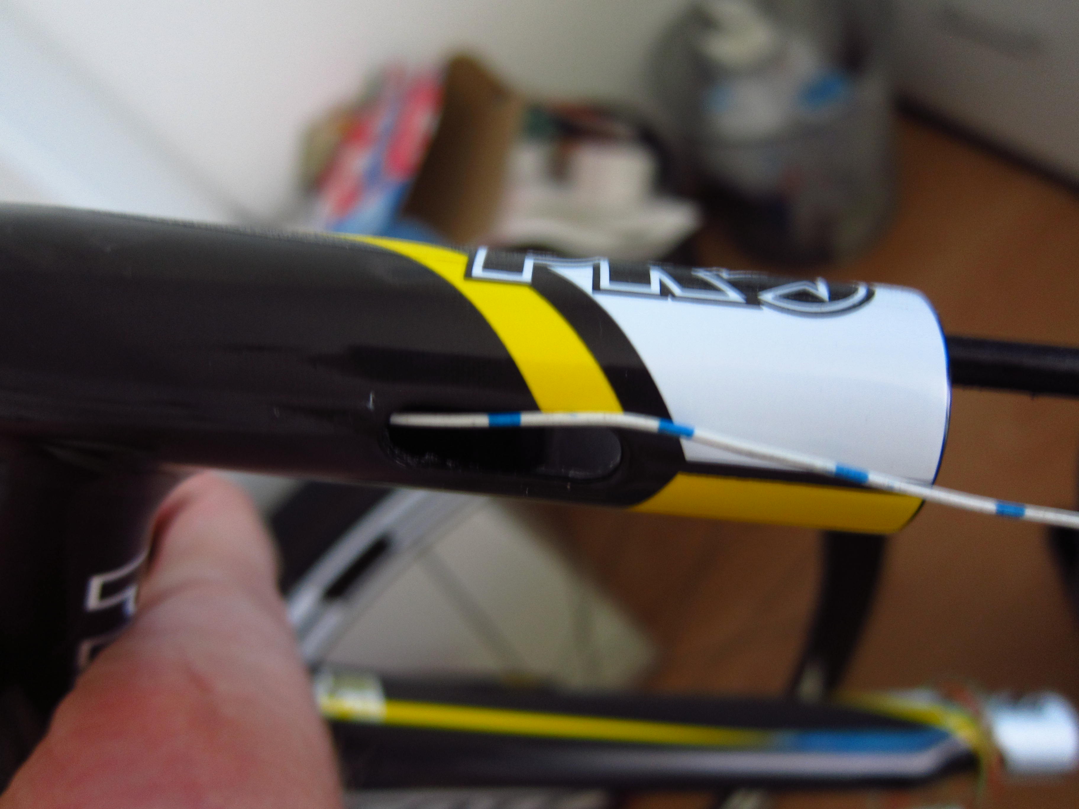
  1. Push rear brake inner wire from bottom bracket to stem, beginning with the plumb
  2. Attach the Di2 cable (950mm) to the brake wire using electric tape and pull back the brake wire from stem to bottom bracket
  3. Loosen Di2 cable
  4. Push rear brake inner wire again from bottom bracket to stem, beginning with the plumb
  5. Push rear brake outer housing over the inner wire, from bottom bracket to stem
  6. Pull out rear brake inner wire
  7. Push outer housing through base bar
  8. Mount brake lever
  9. Push inner wire through brake lever, base bar and stem to the bottom bracket. Recommendation: Do not attach base bar to stem or stem to fork before doing that. The radius of the outer housing will be small which makes pushing the inner cable through nearly impossible.

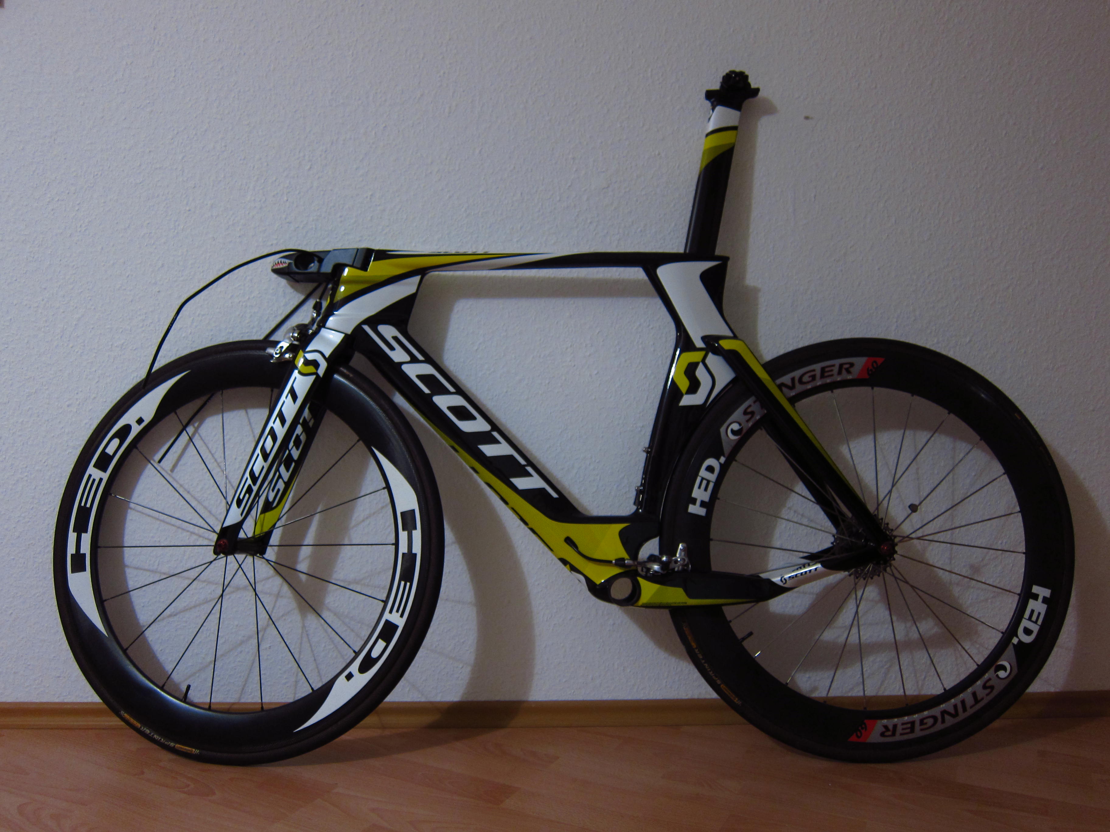
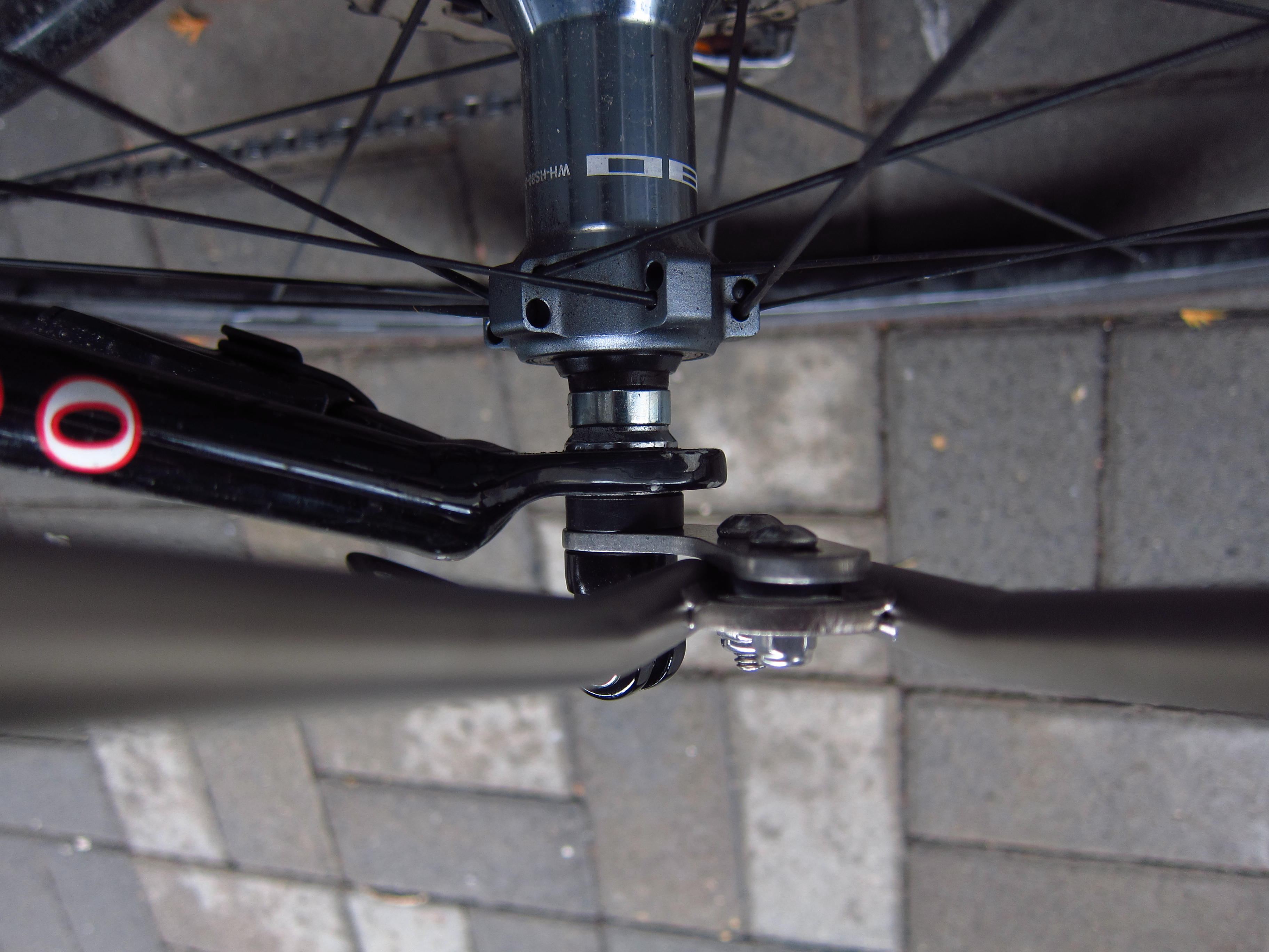
With wheels and seatpost mounted, it starts to look like a bike.

20131024_Scott-Plasma-TT_17

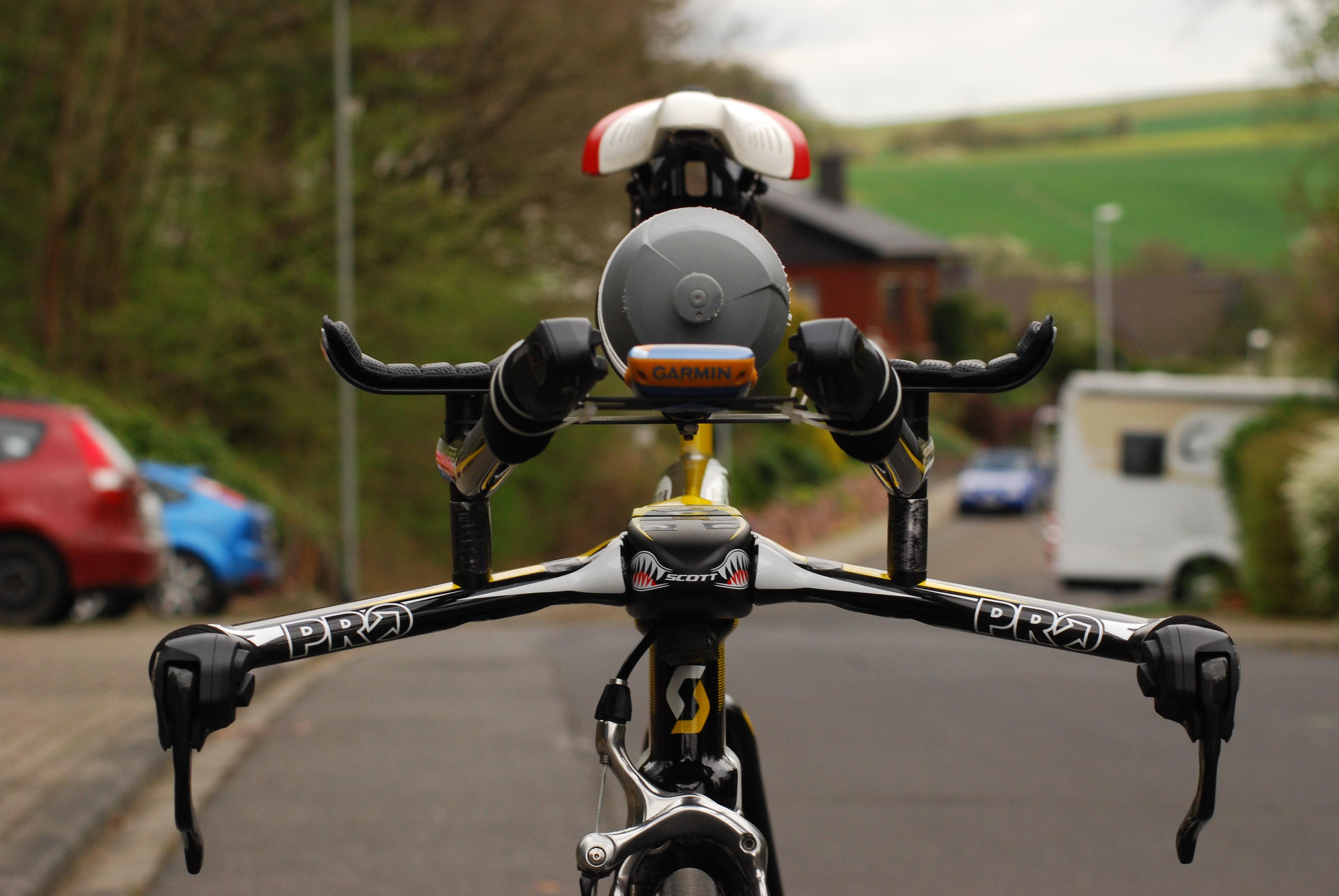
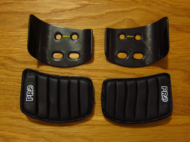
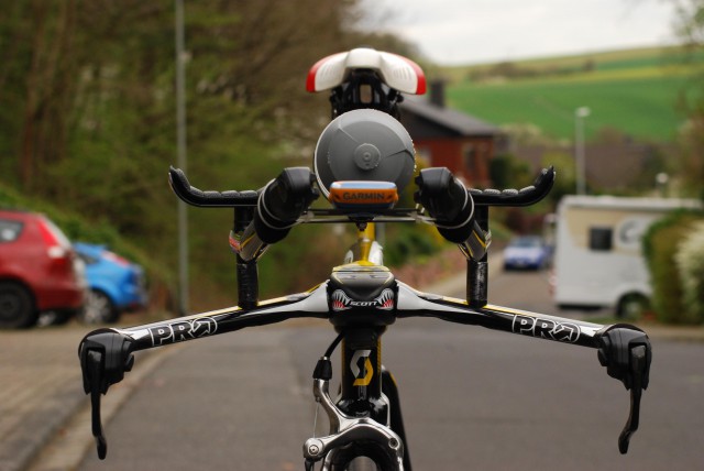
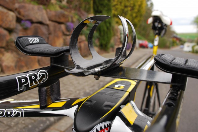
The carbon pad holders are mounted directly to the extensions. The gel pads appear to be quite comfortable.

20131024_Scott-Plasma-TT_18

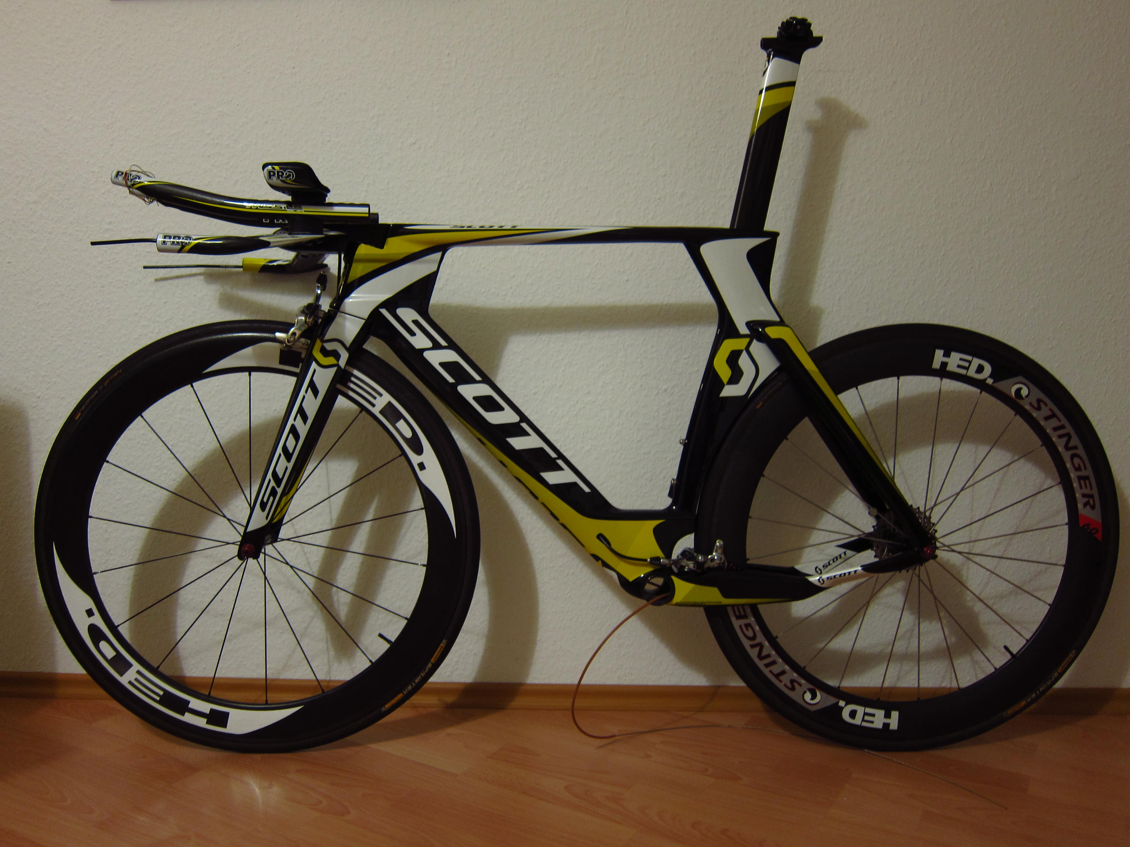
With basebar and extensions mounted, all I wanted to do is riding this bike as soon as possible.

20131024_Scott-Plasma-TT_19

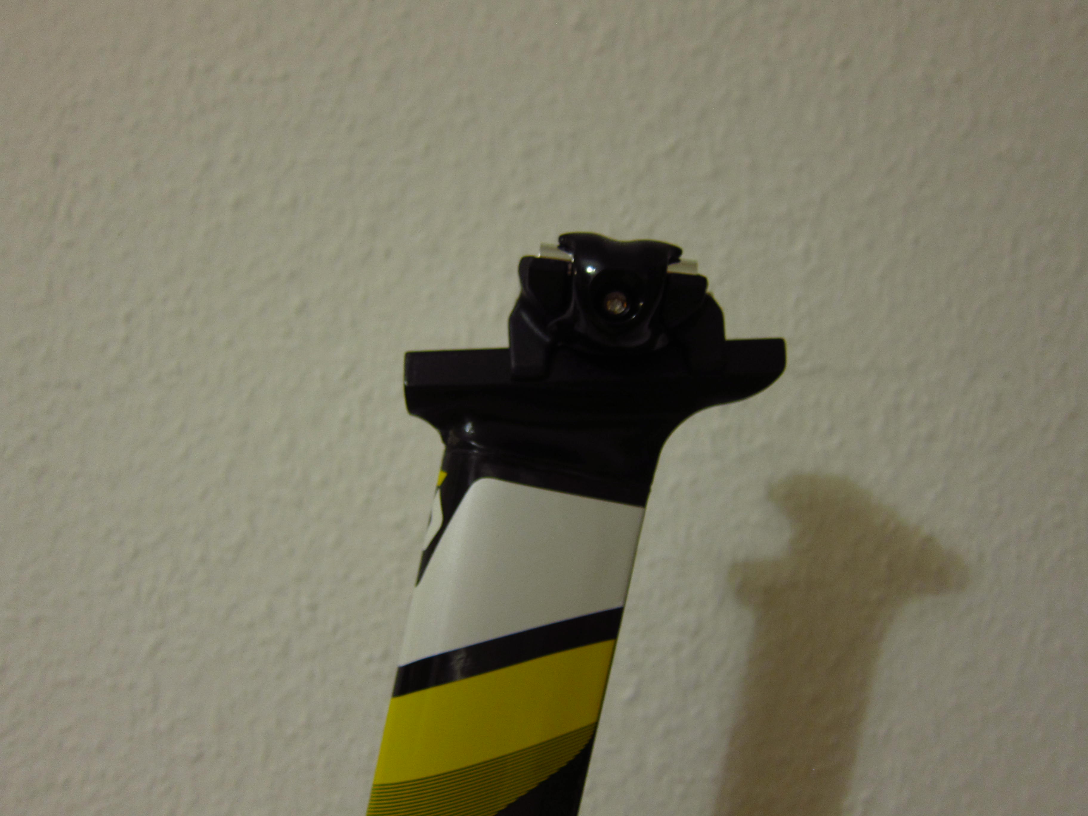
Wait, a saddle would be helpful as well – the Ritchey Seat Post mount proved to be a little bit fiddly.

20131024_Scott-Plasma-TT_20

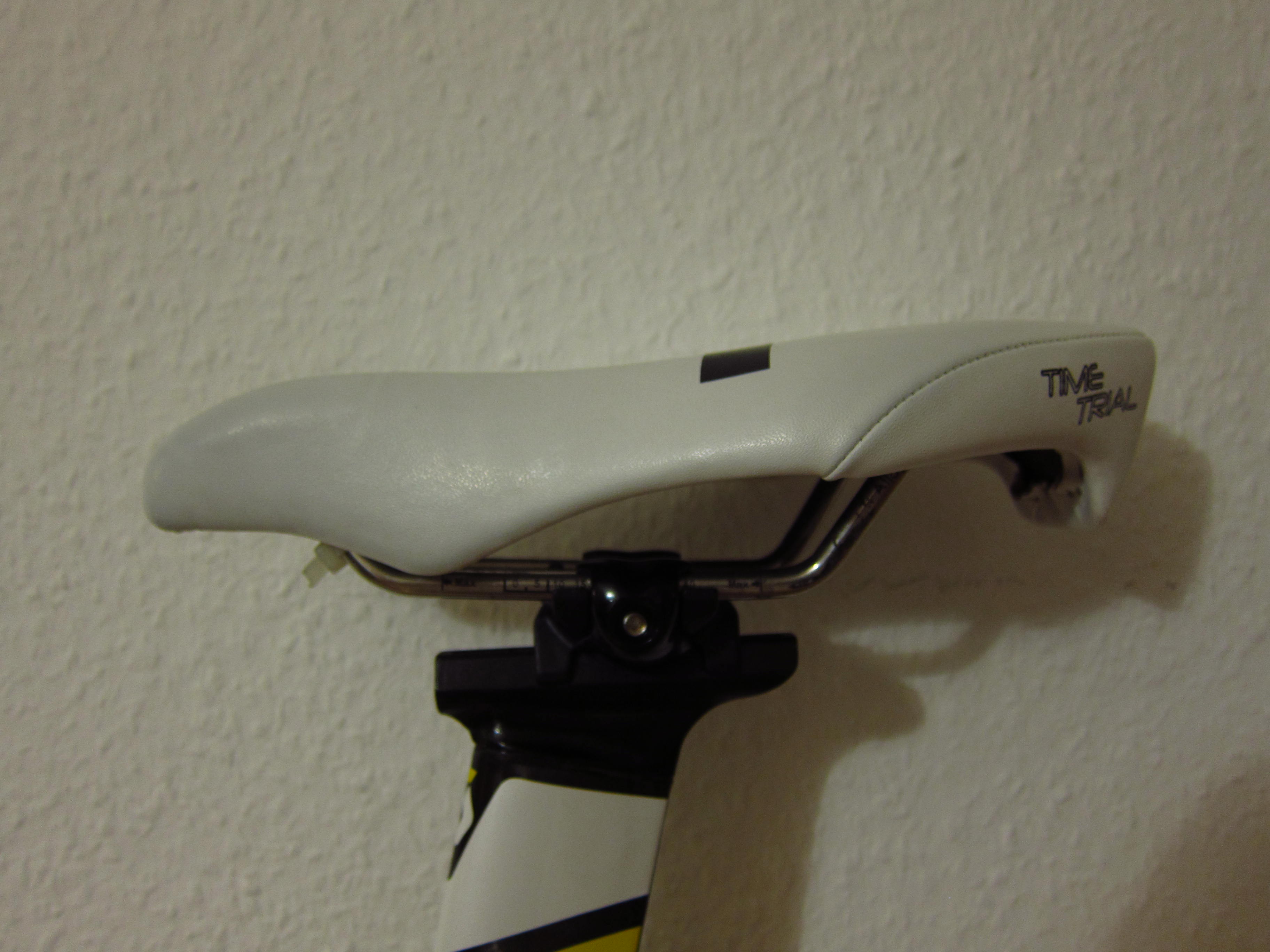
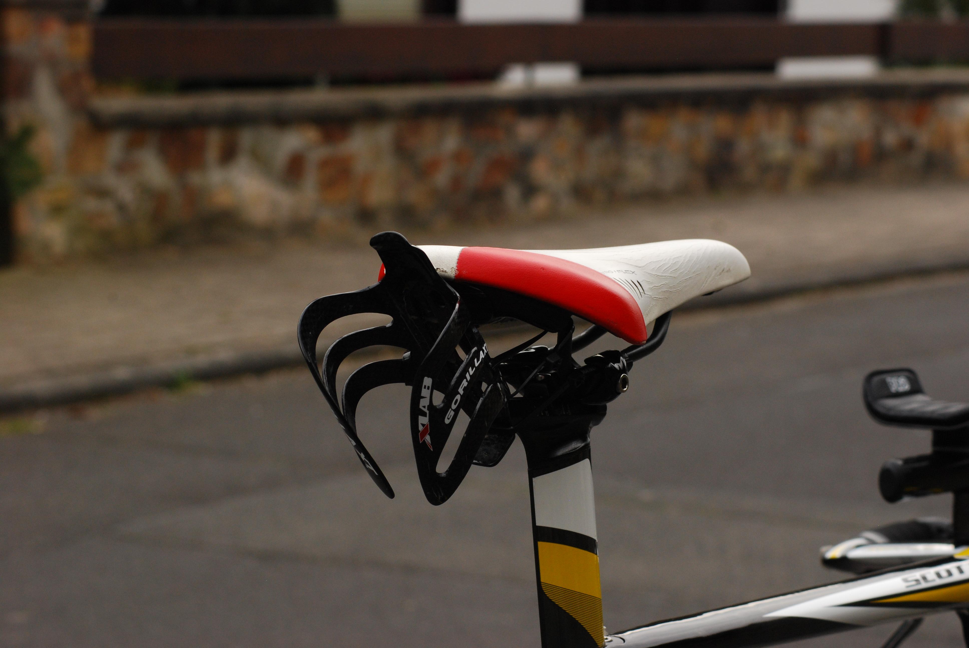
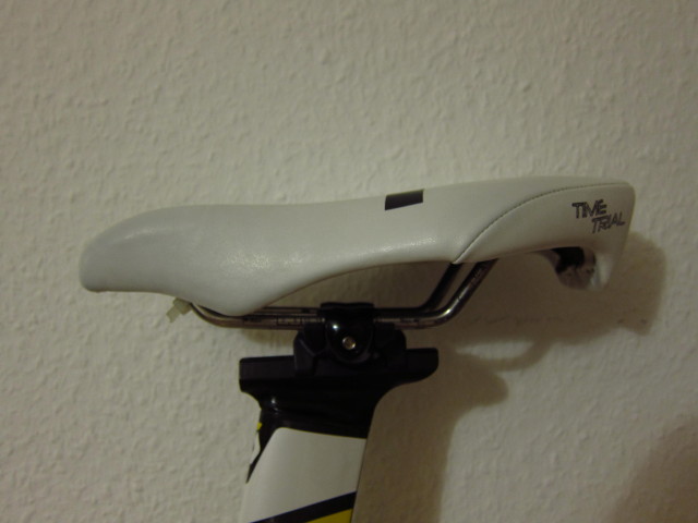
I will reuse my ISM Adamo Time Trial saddle also on the new bike.

20131024_Scott-Plasma-TT_21

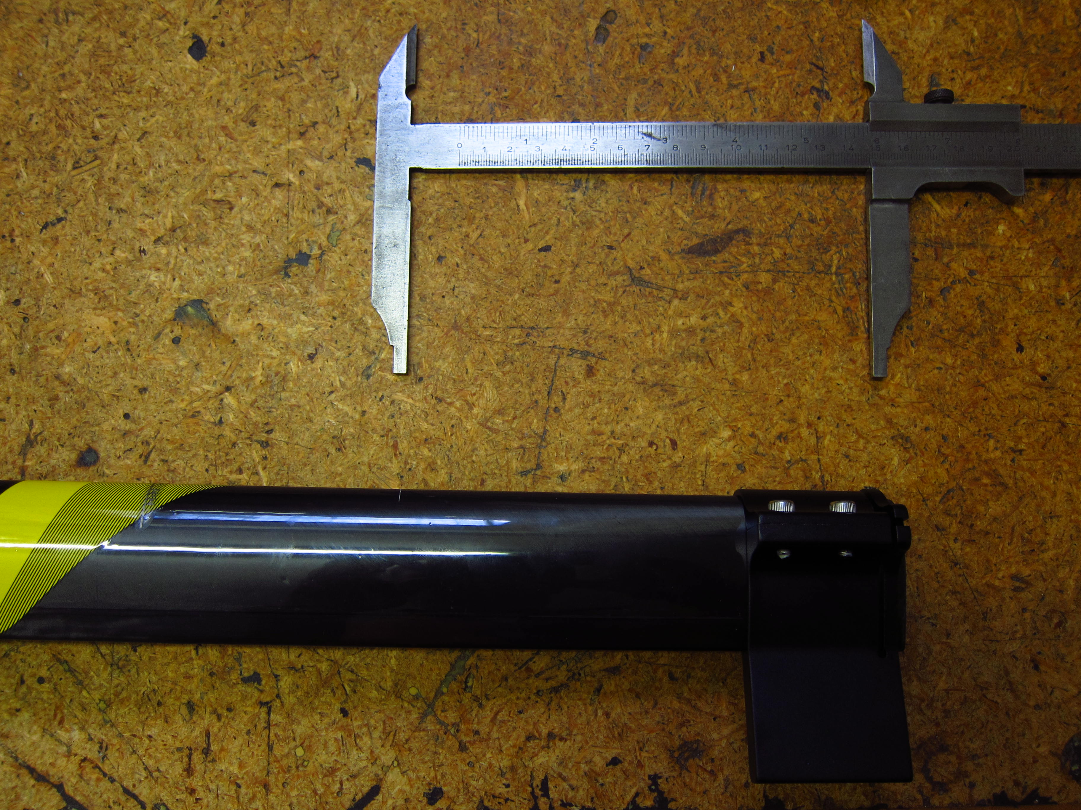
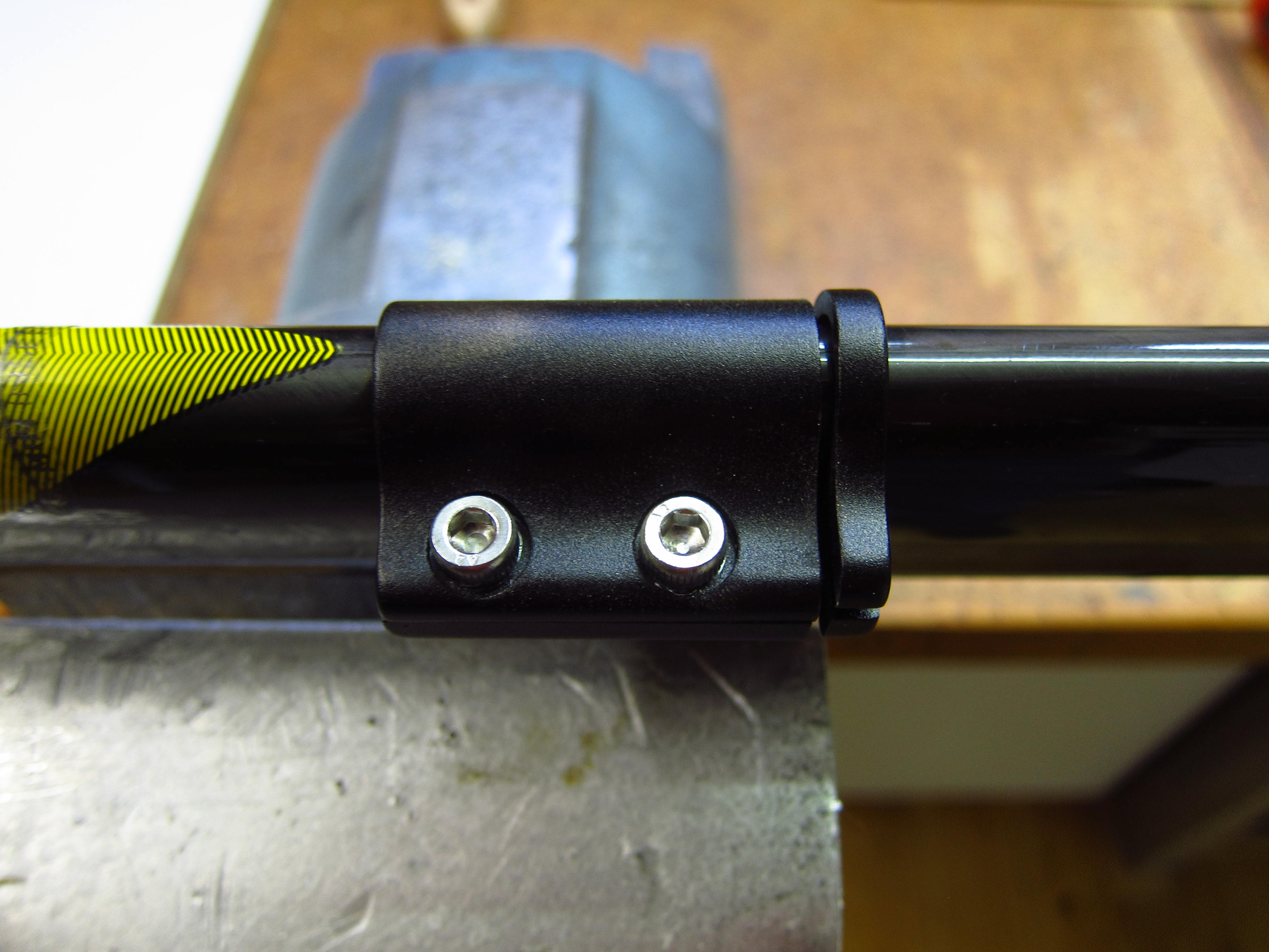
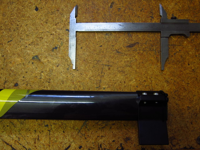
To cut the seatpost to it’s correct length, I measured the distance between pedal axle and top of the saddle on my old bike and afterwards measured the same distance on the new bike with the uncut seatpost. The difference between these two measures was the distance I needed to cut off. I marked this distance with a caliper.

20131024_Scott-Plasma-TT_211

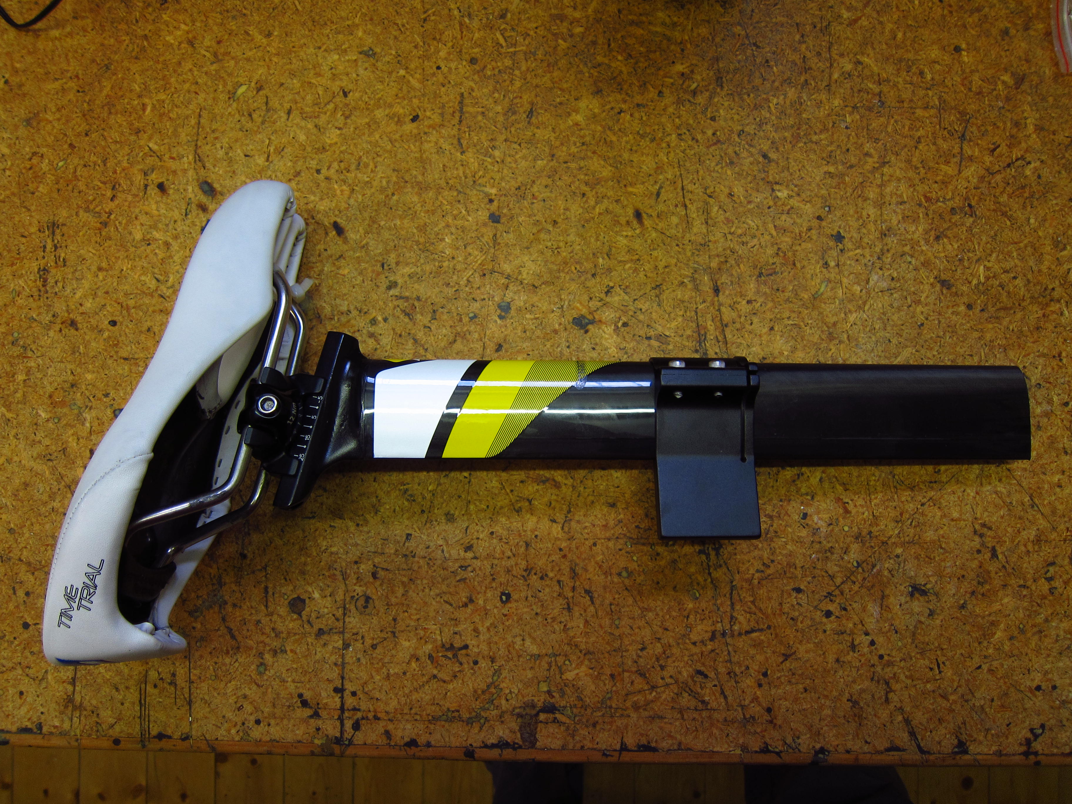
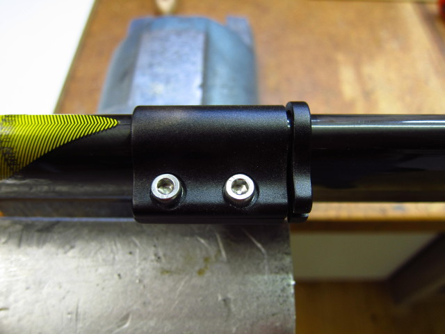
Afterwards, I moved the cutting tool to the mark and fastened the two bolts.

20131024_Scott-Plasma-TT_212

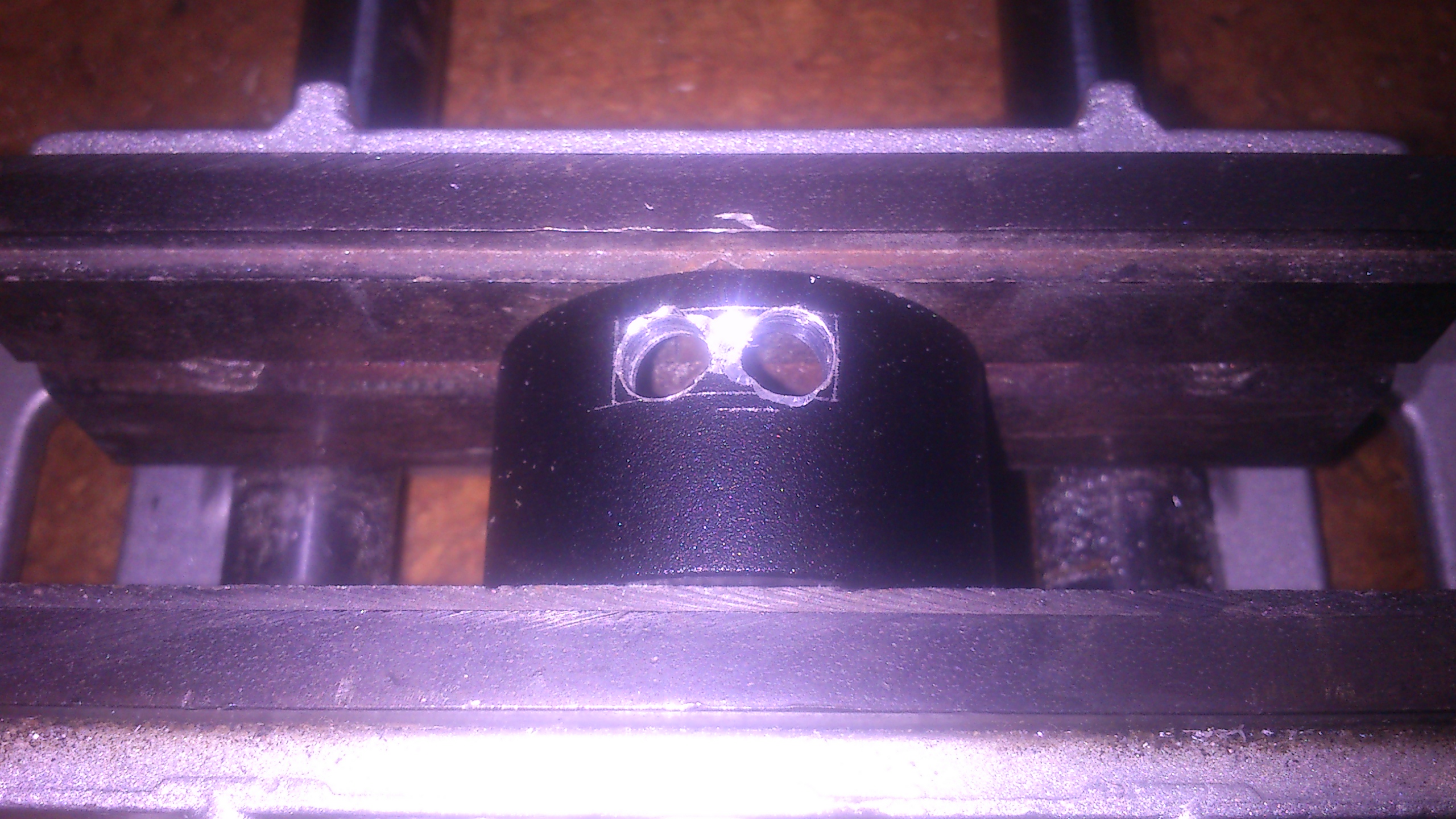
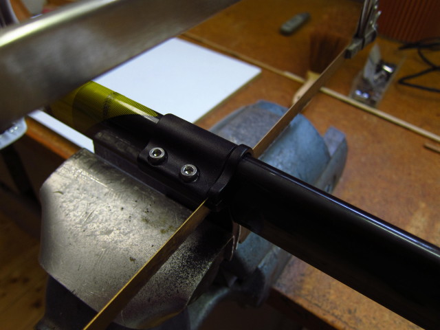
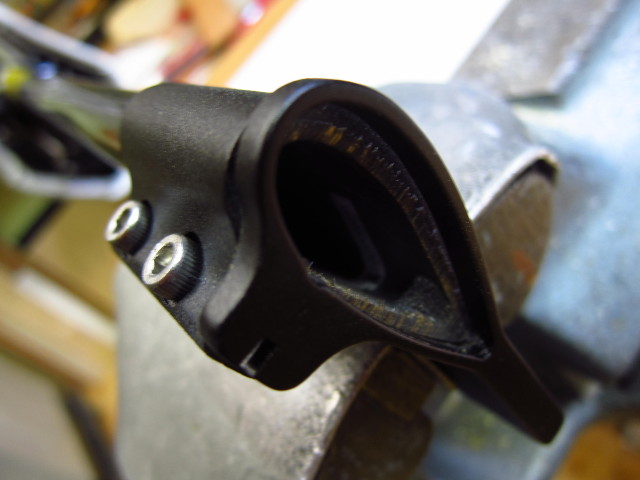
Then, I fastened the cutting tool in a bench vice.

20131024_Scott-Plasma-TT_213

Time for the saw.

20131024_Scott-Plasma-TT_214

After a few minutes, the cut was complete.

20131024_Scott-Plasma-TT_215

After installing the basic components, the more delicate part of the build commenced: The installation of Shimano Ultegra Di2 electronic shifting components.

20131024_Scott-Plasma-TT_22

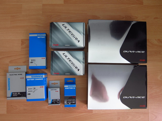
Those consisted out of the JC-41 Rear Junction Box,…

20131024_Scott-Plasma-TT_23

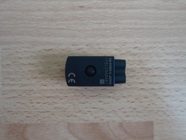
the SM-EW-90A Front Junction Box,…

20131024_Scott-Plasma-TT_24

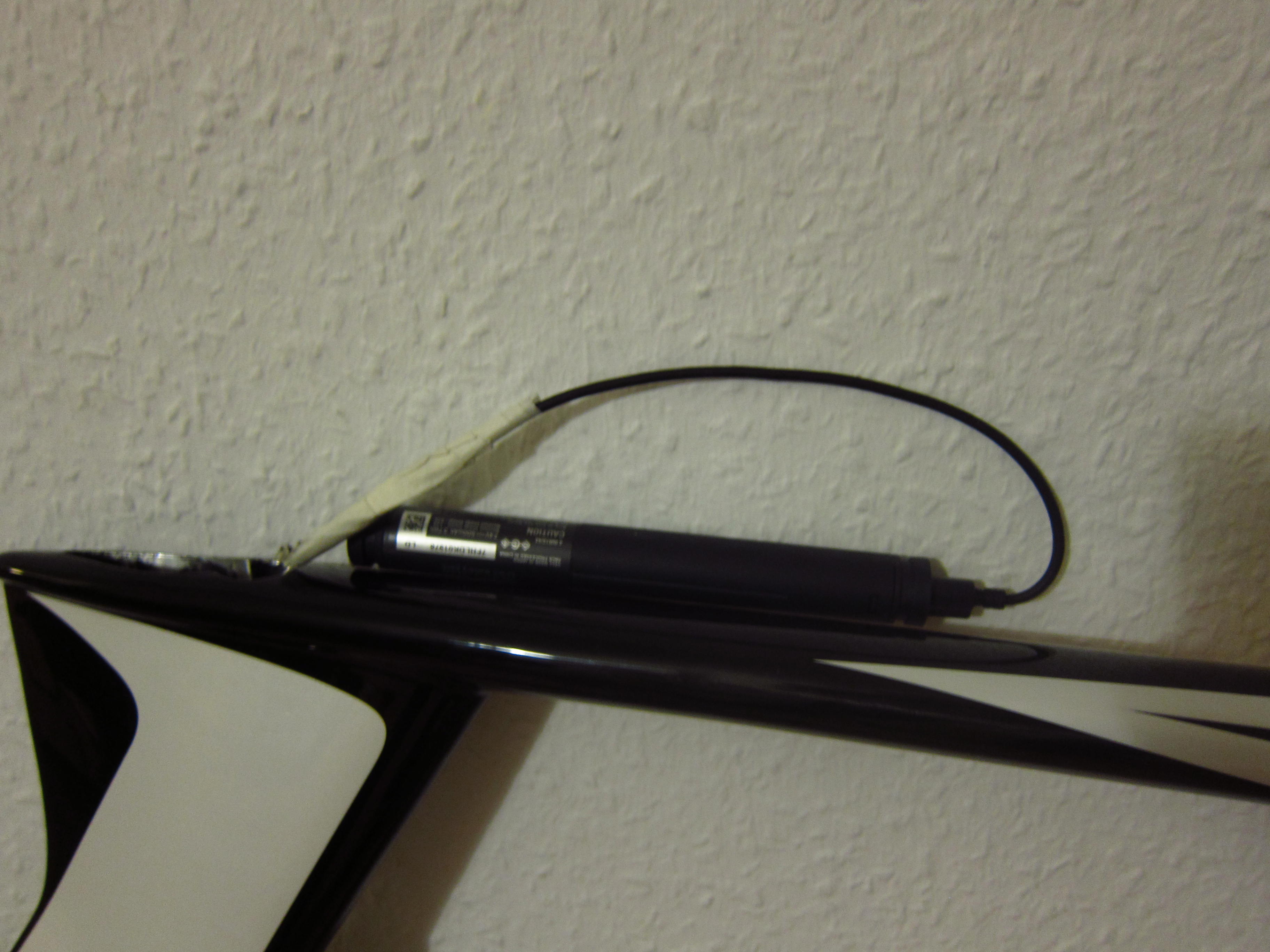
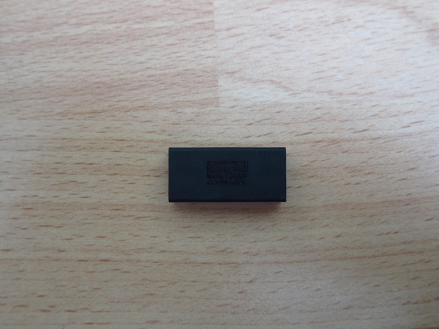
the SM-BTR-2 internal battery,…

20131024_Scott-Plasma-TT_25

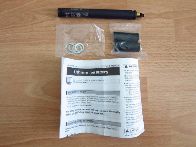
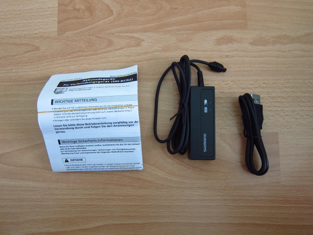
the SM-BCR-2 charger an PC connection,…

20131024_Scott-Plasma-TT_26

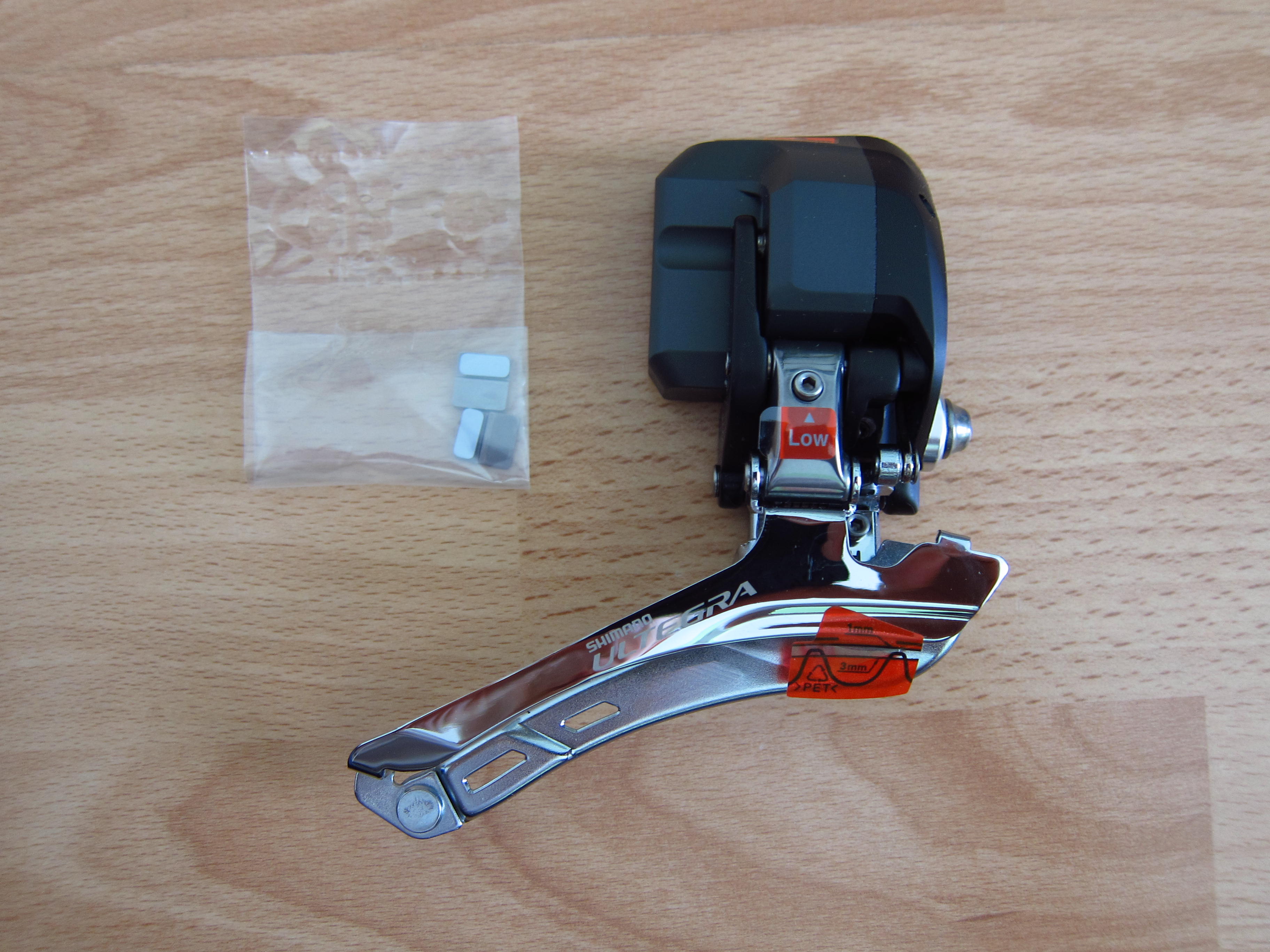
the FD-6770 front derailleur,…

20131024_Scott-Plasma-TT_27

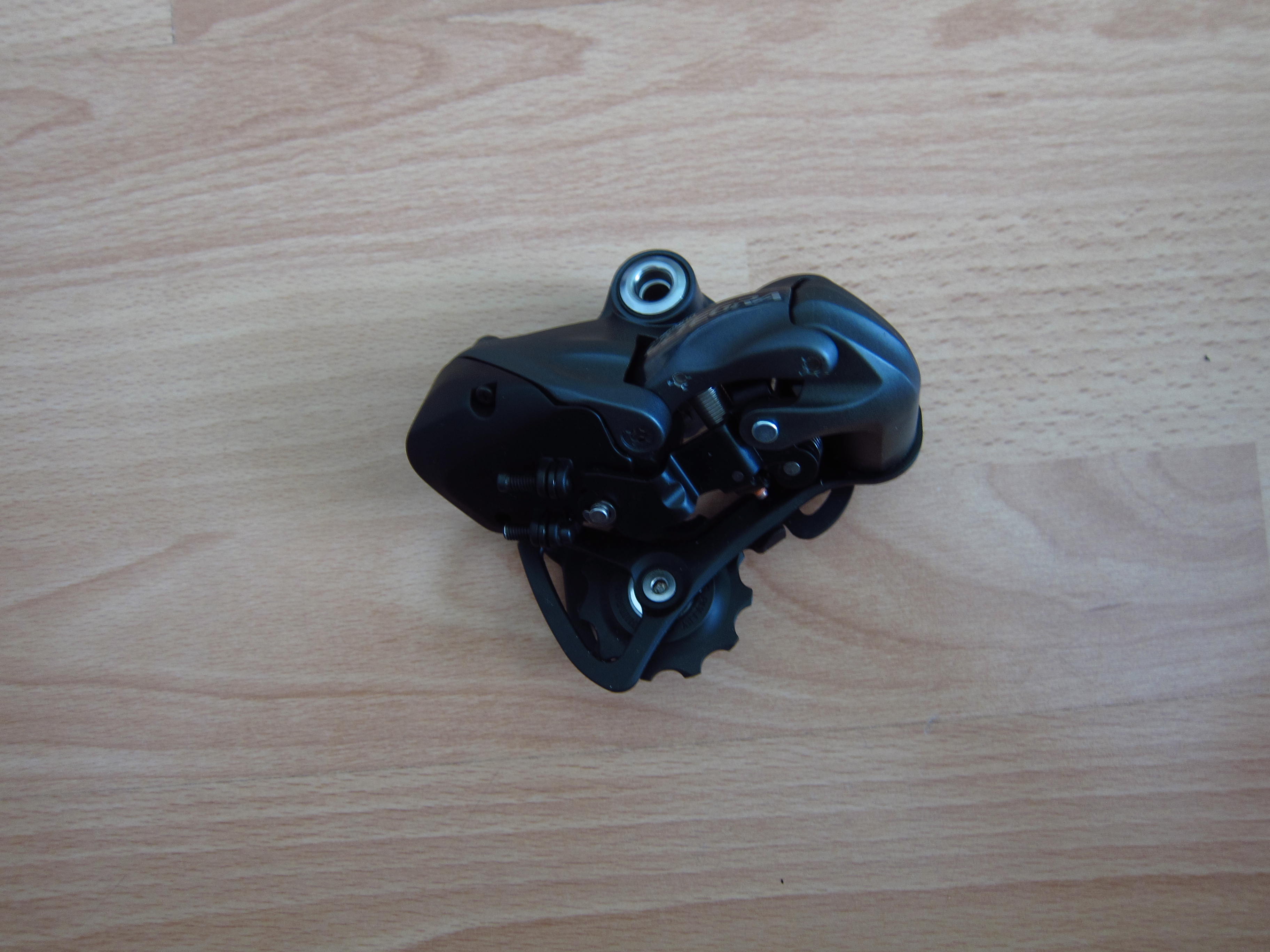
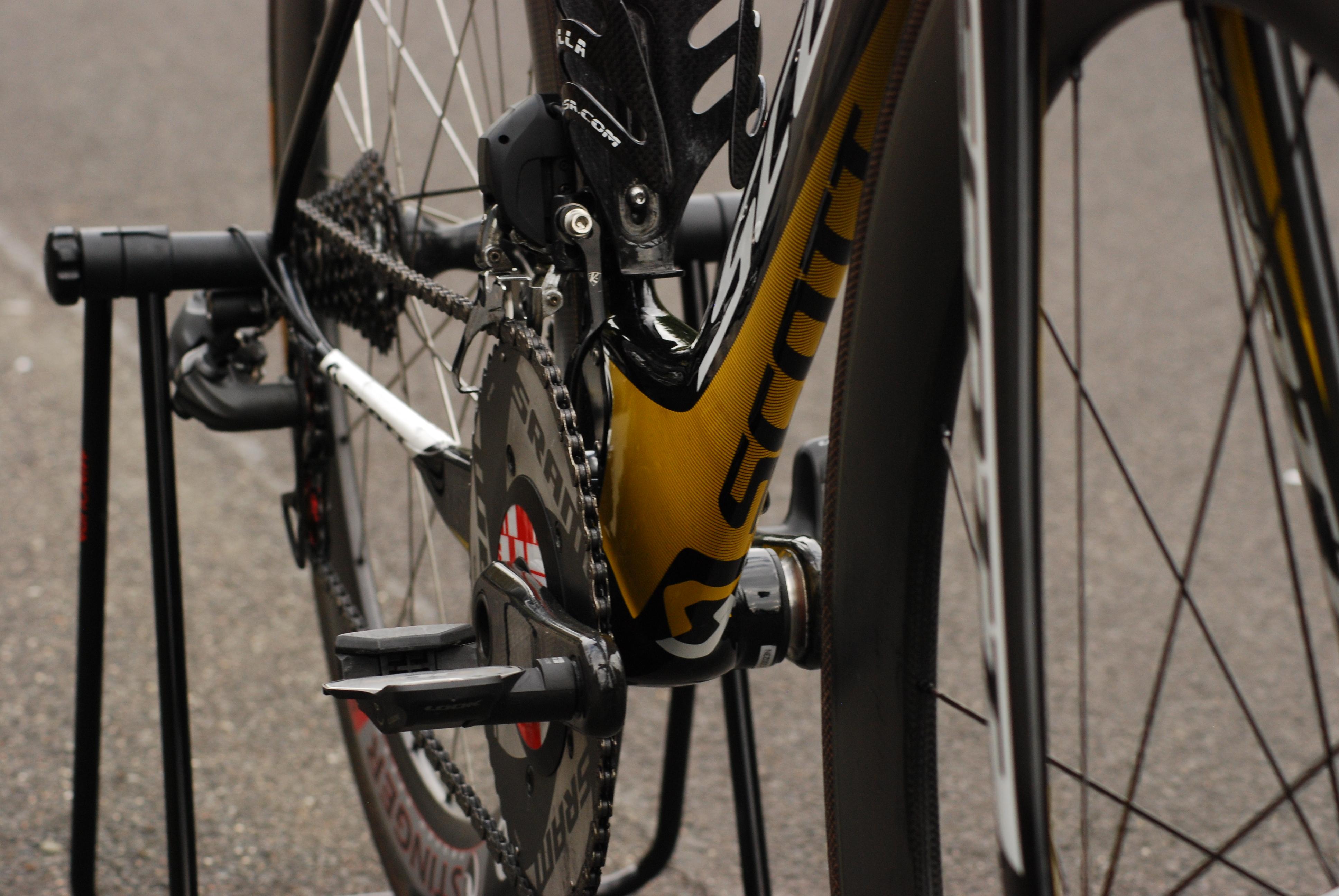
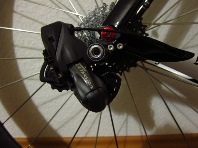
the RD-6770 rear derailleur,…

20131024_Scott-Plasma-TT_28

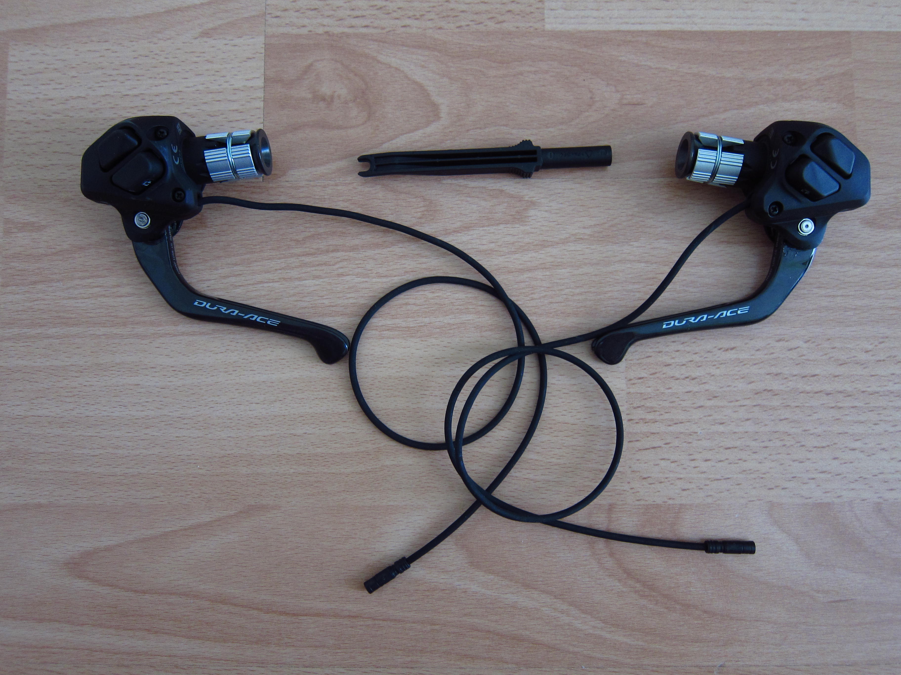
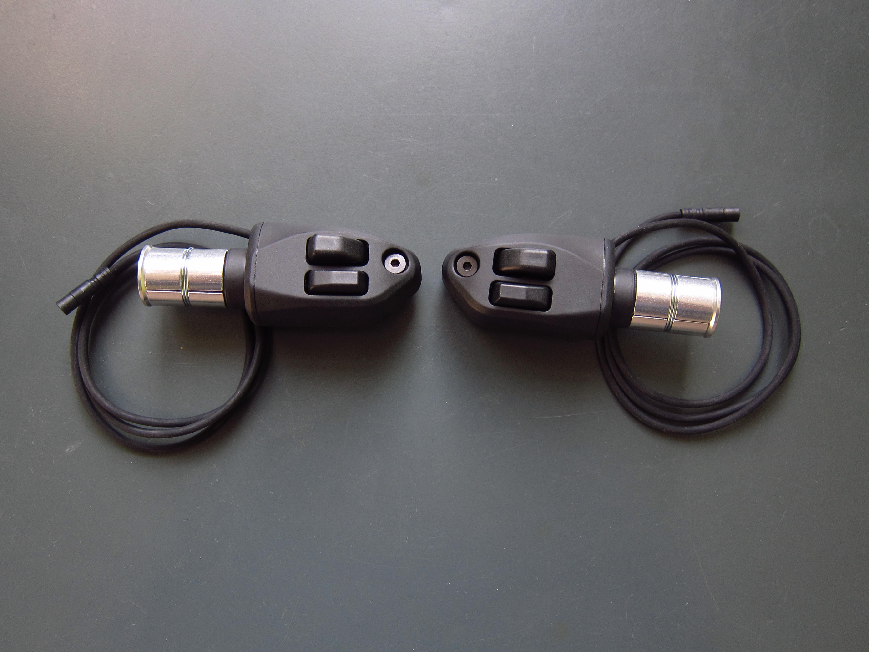
the ST-9071 brake shift levers and…

20131024_Scott-Plasma-TT_29

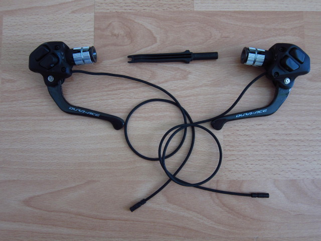
last not least the ST-R671 extension shifters.

20131024_Scott-Plasma-TT_30

The rear derailleur installation was quite easy, just one bolt which needs to be tightened against the RD hanger. The cable was routed from the rear entry to the bottom bracket, a cable length of 500mm is sufficient.

20131024_Scott-Plasma-TT_31

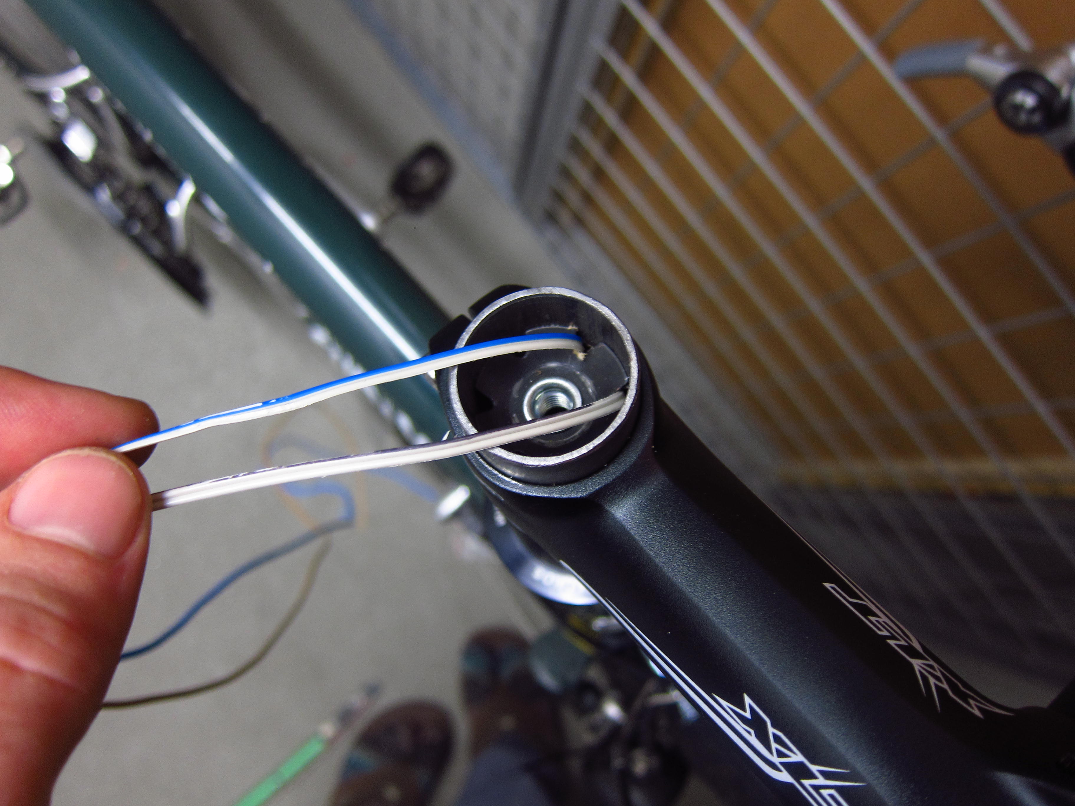
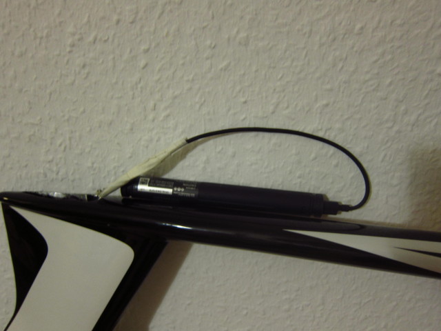
The internal battery was put into the seatpost. A cable length of 250mm is sufficient. However, to get the battery cable to the bottom, I had to route a brake cable from the bottom bracket to the seat post and pull the battery cable trough.

20131024_Scott-Plasma-TT_33

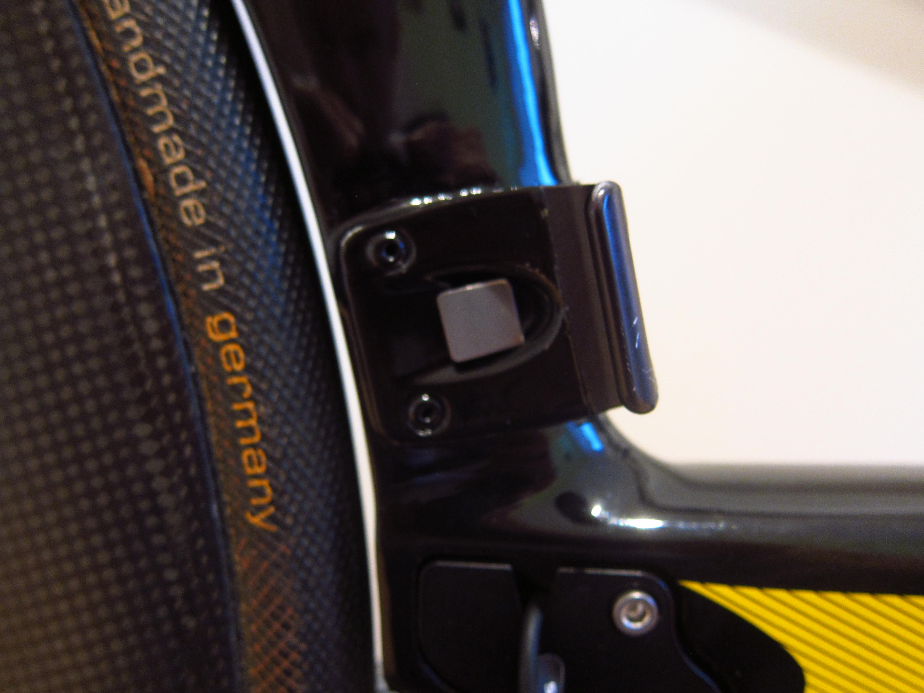
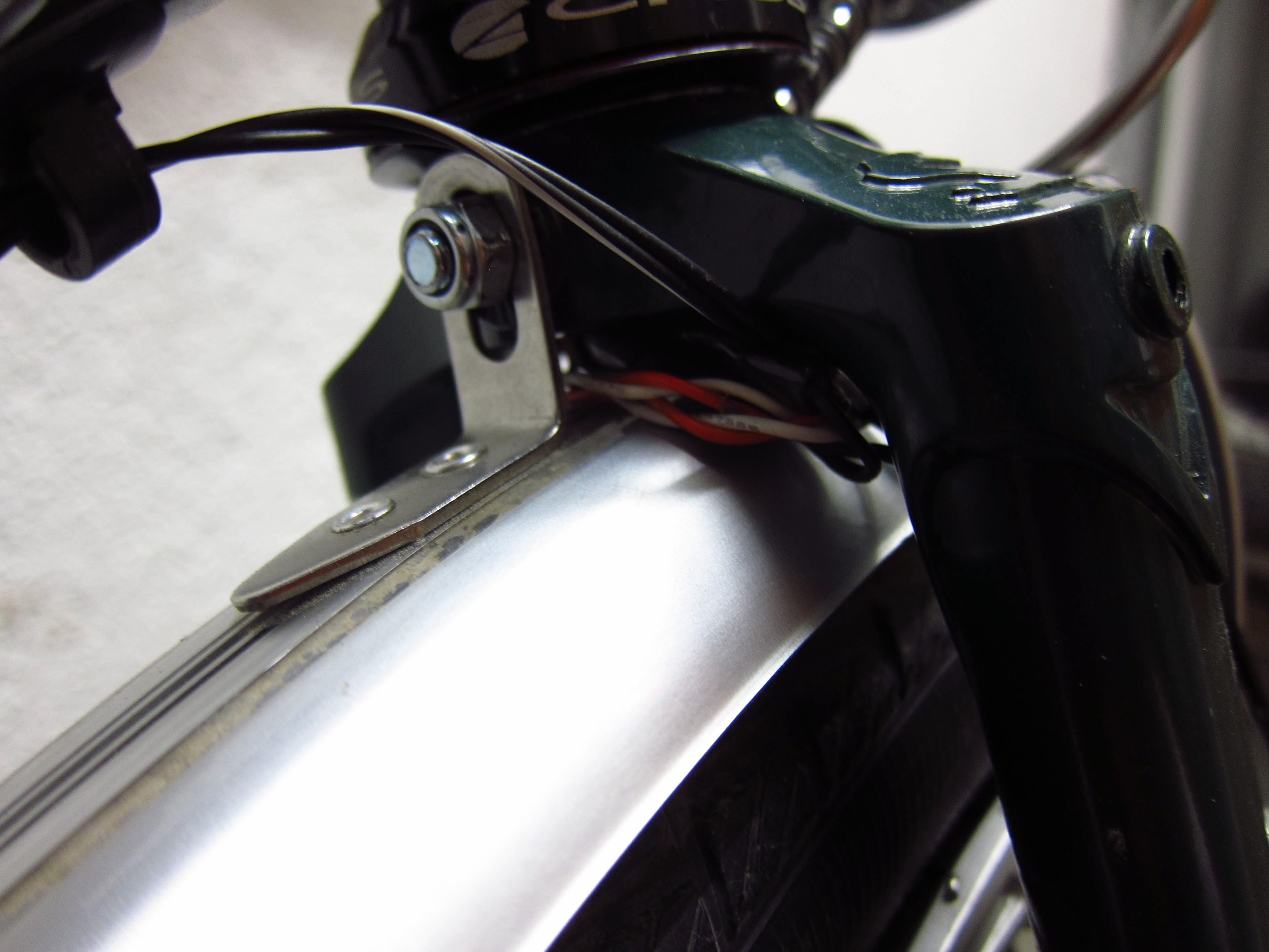
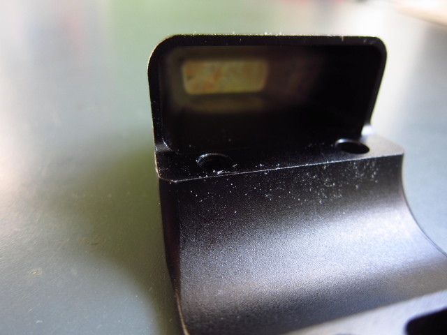
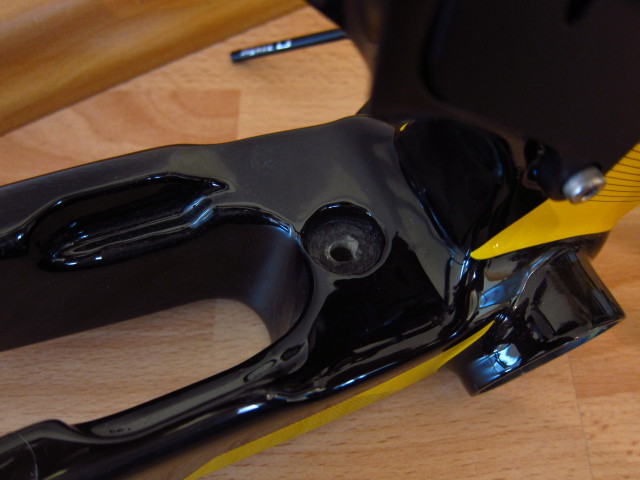
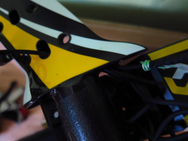
To mount the front derailleur, first of all a small metal plate needs to be attached to the frame.

20131024_Scott-Plasma-TT_34

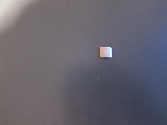
This plate is for the front derailleur to push against.

20131024_Scott-Plasma-TT_341

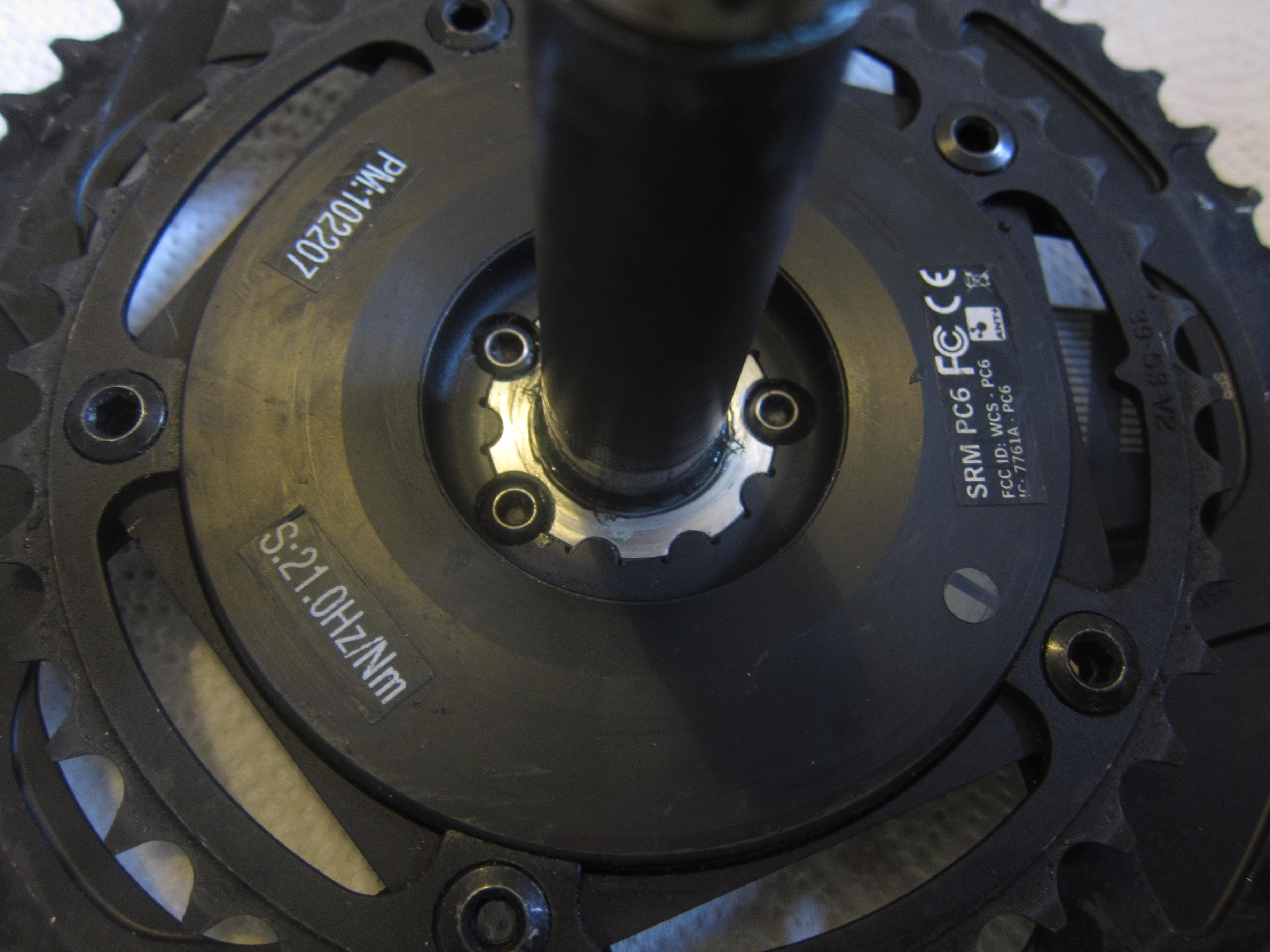
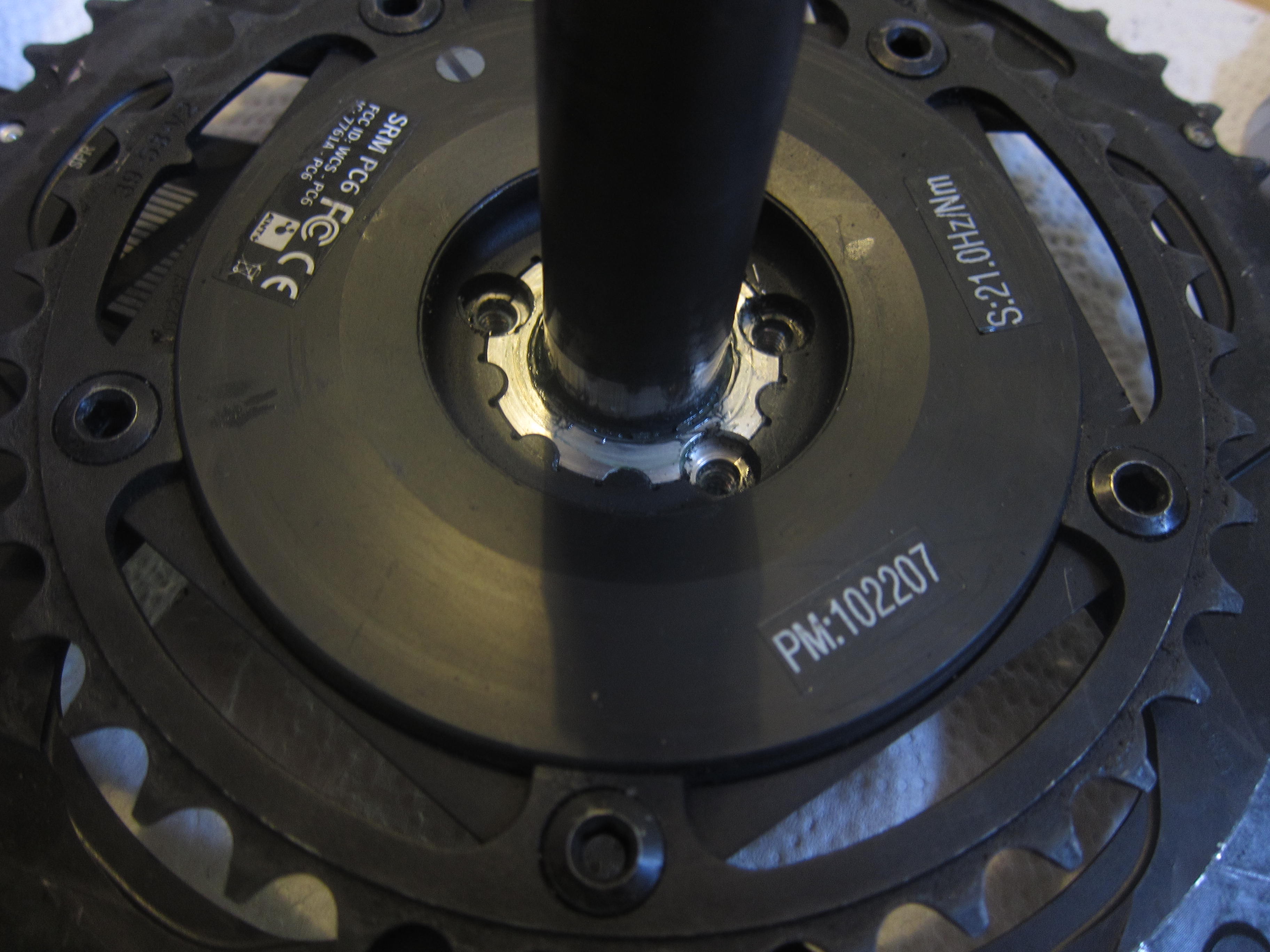
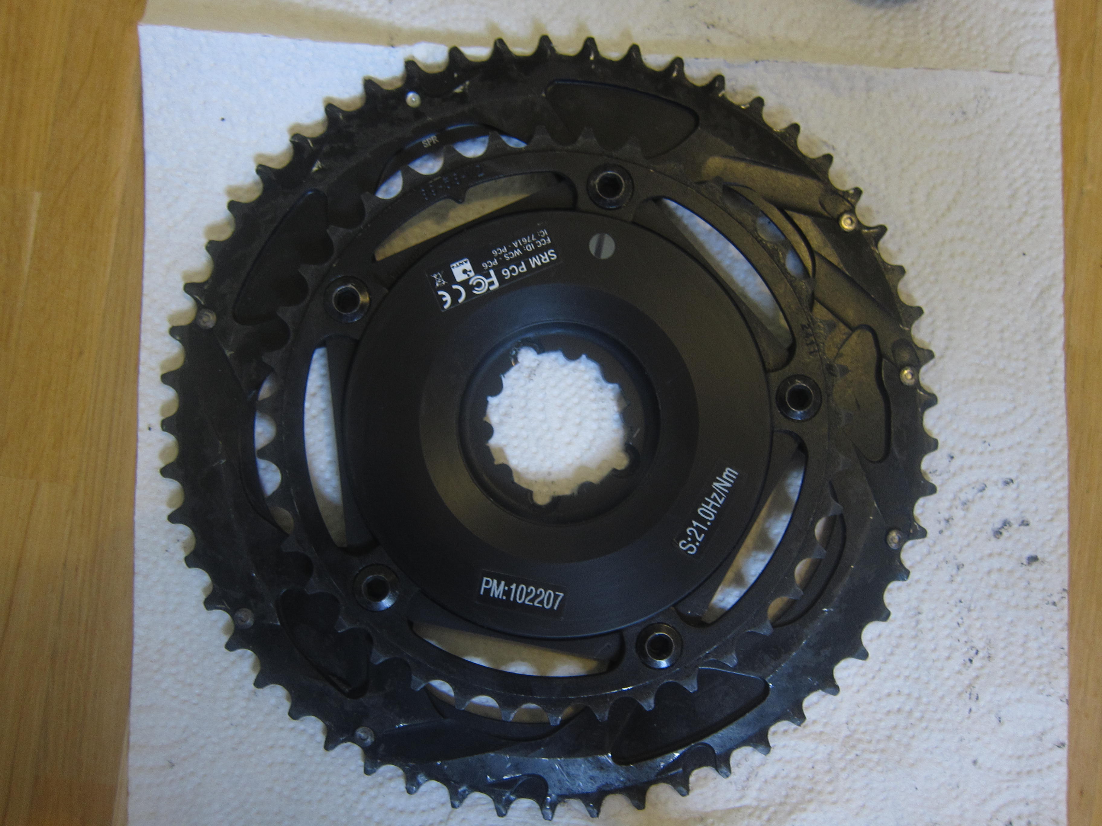
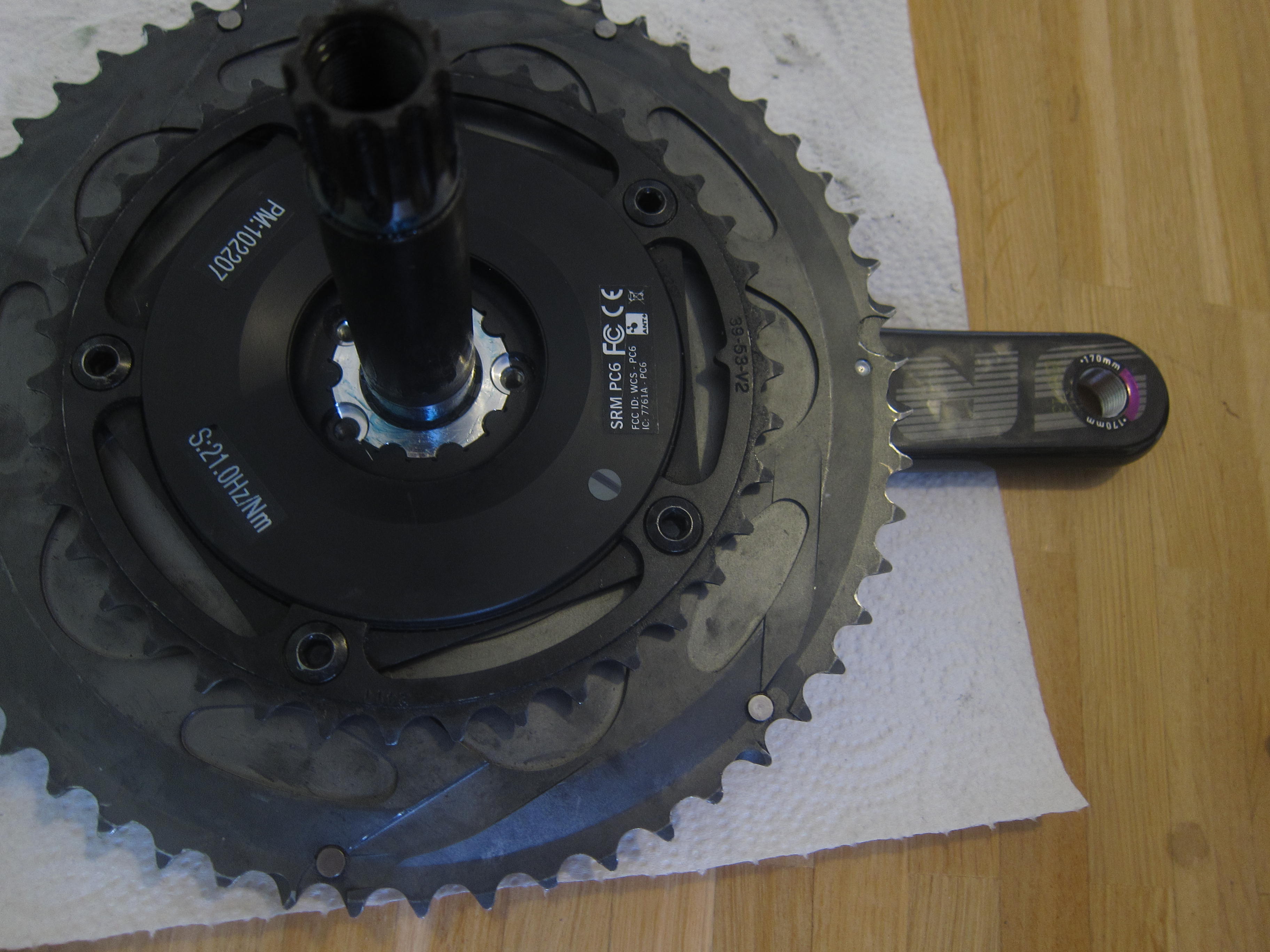
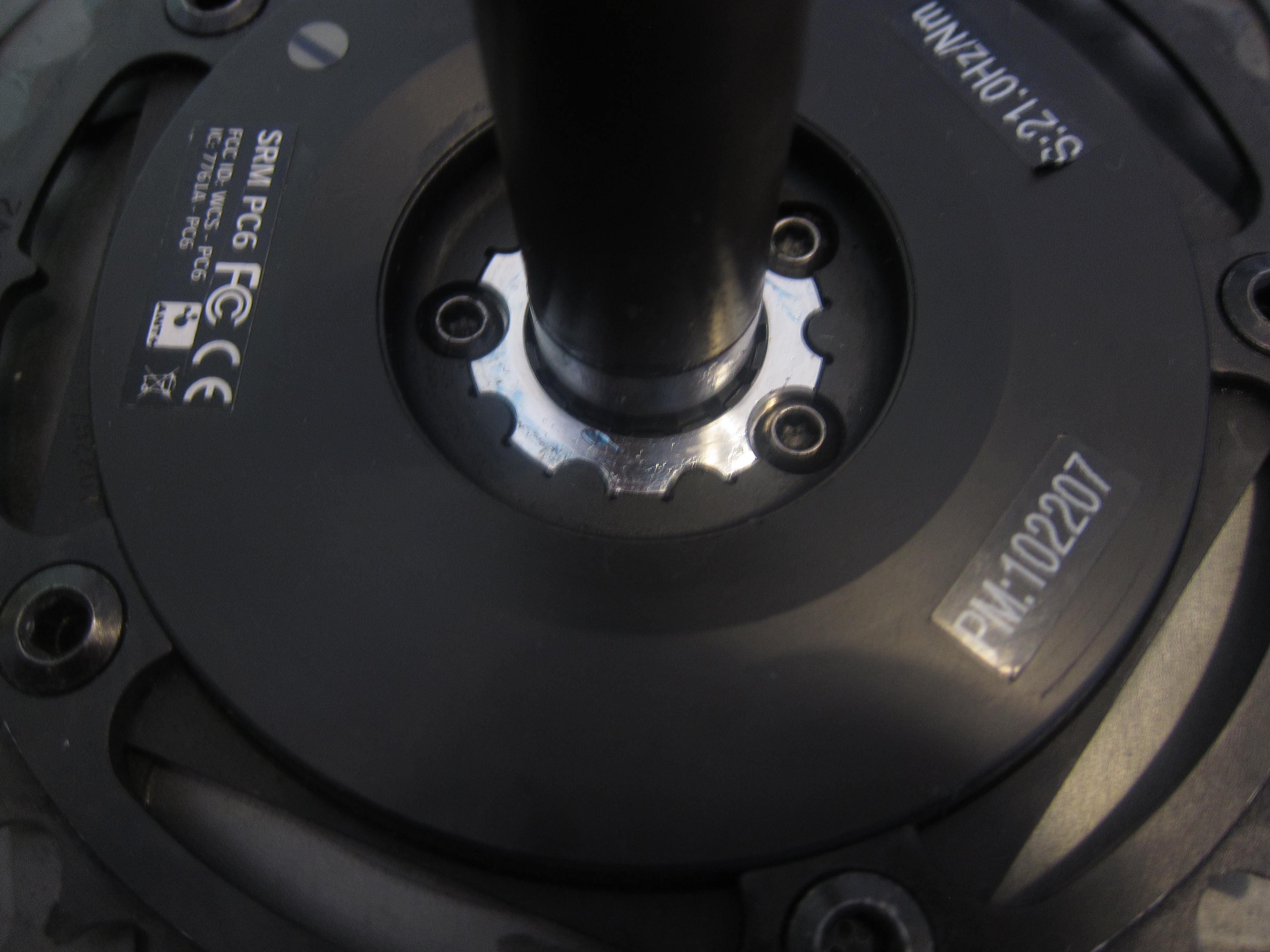
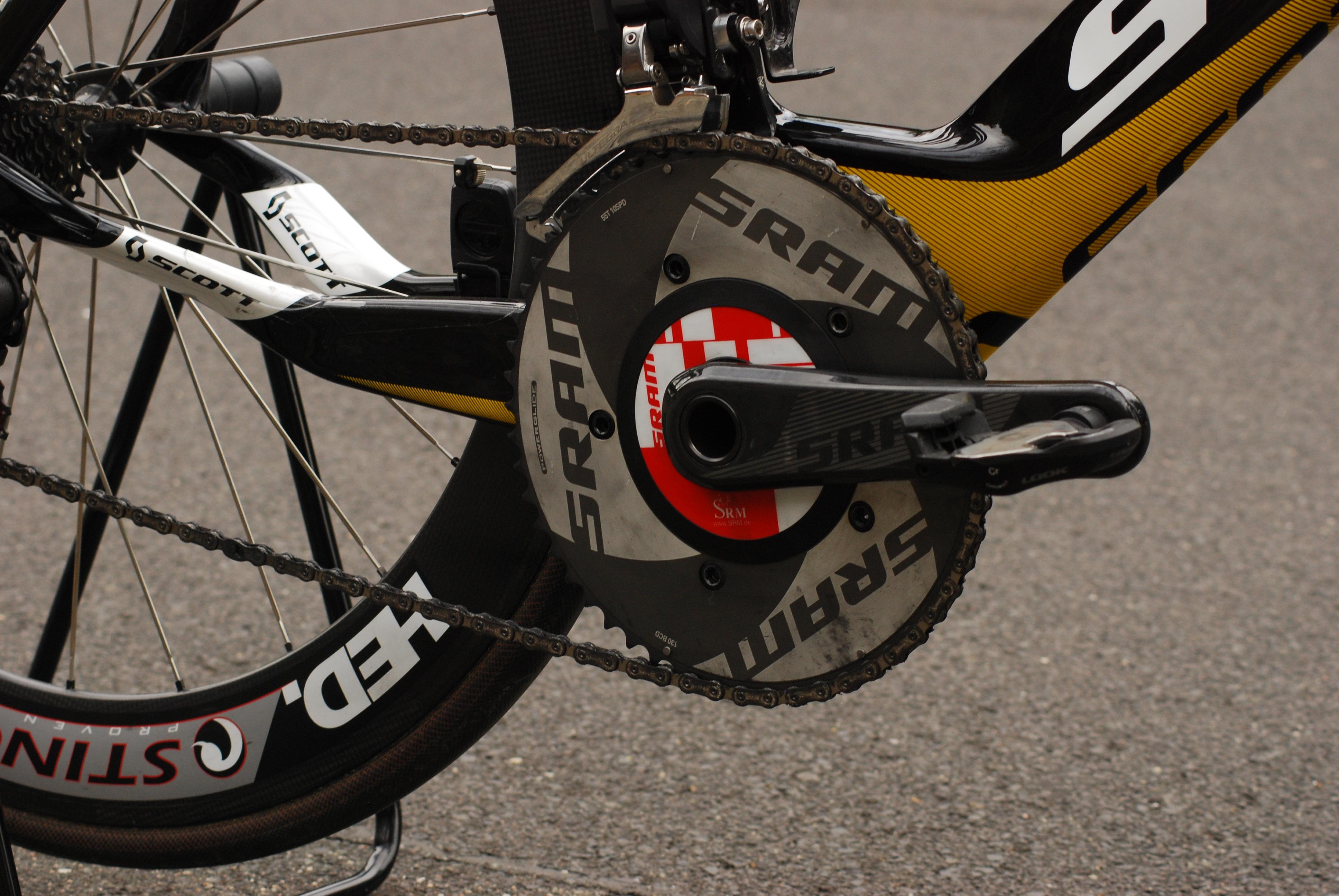
After both derailleurs and the battery were installed, I connected all wires to the rear junction box and pulled one cable from the stem to the rear junction box. Finally, the bottom bracket and the crank could be installed. I reused the SRM SRAM GXP S975 Powermeter which was already installed on my previous bike.

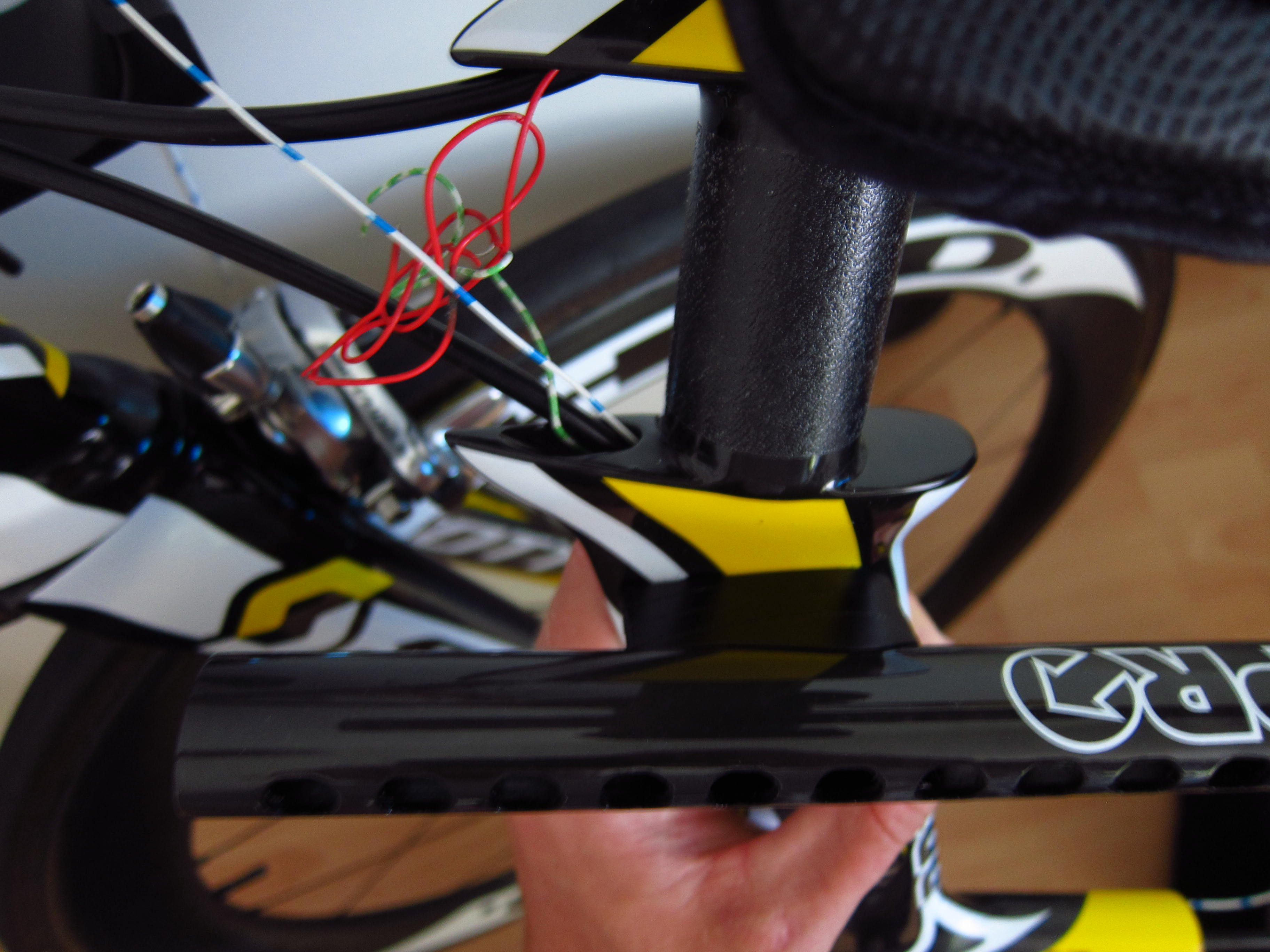
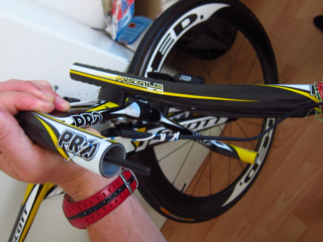
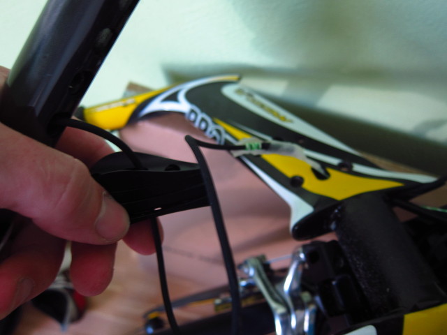
Now comes the rather tricky part – installing all cables in the base bar and the extensions. I started with pushing through the outer brake cables from the stem to the bull horns. Afterwards, I pushed through tiny cables to pull back the shifter wires.

20131024_Scott-Plasma-TT_35

Pushing the cables through the bull horns…

20131024_Scott-Plasma-TT_36

and pulling back the Di2 wires.

20131024_Scott-Plasma-TT_37

The first plug comes out of the base bar – three more to go.

20131024_Scott-Plasma-TT_39

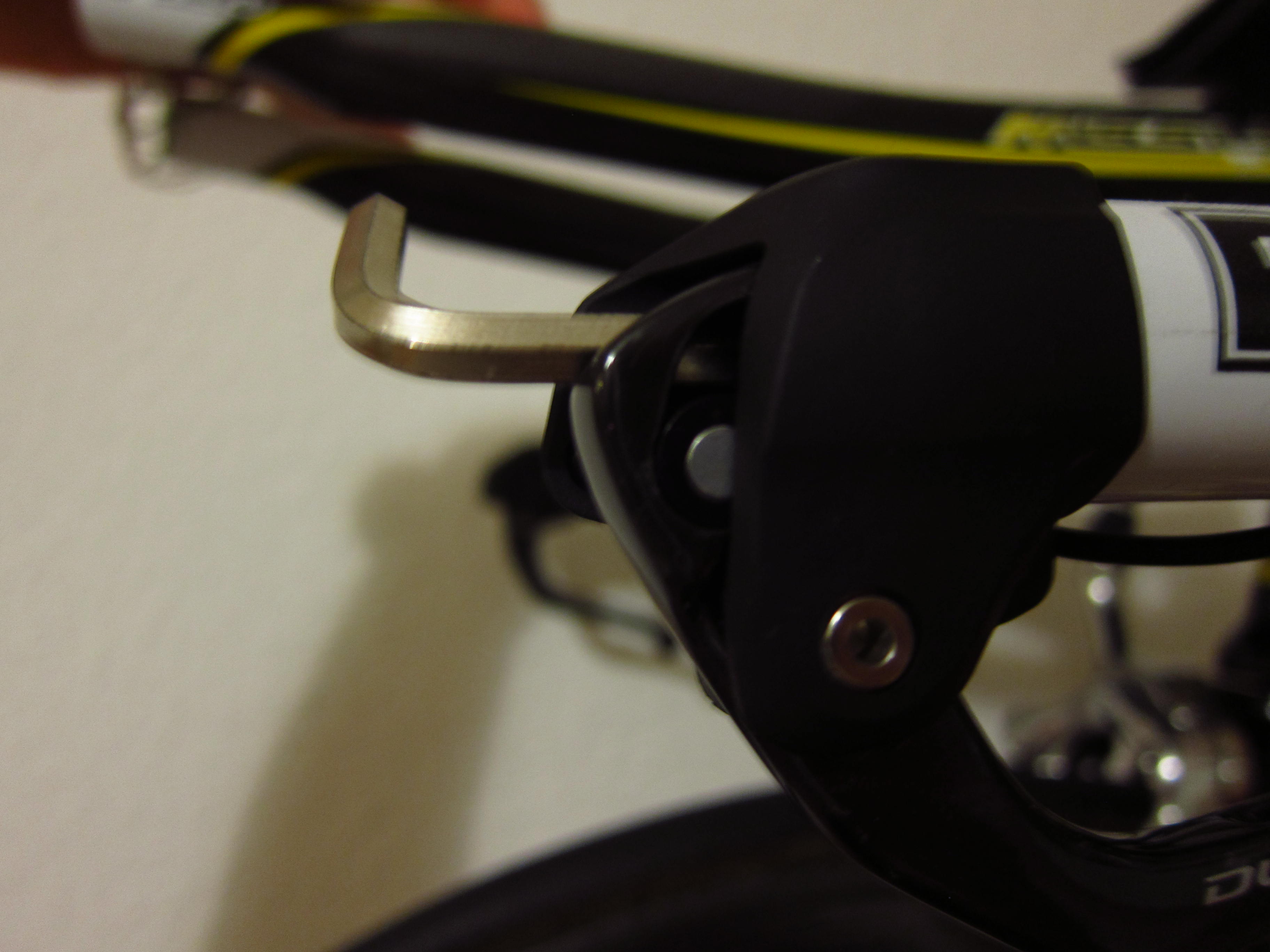
The brake shift lever dangling around the bull horn.

20131024_Scott-Plasma-TT_40

And fixed with a hex key.

20131024_Scott-Plasma-TT_41

The extension shifters mounted to the extensions.

20131024_Scott-Plasma-TT_43

The extension shifter cables have to run trough the spacers beneath the extensions…

20131024_Scott-Plasma-TT_44

and trough the basebar.

20131024_Scott-Plasma-TT_46

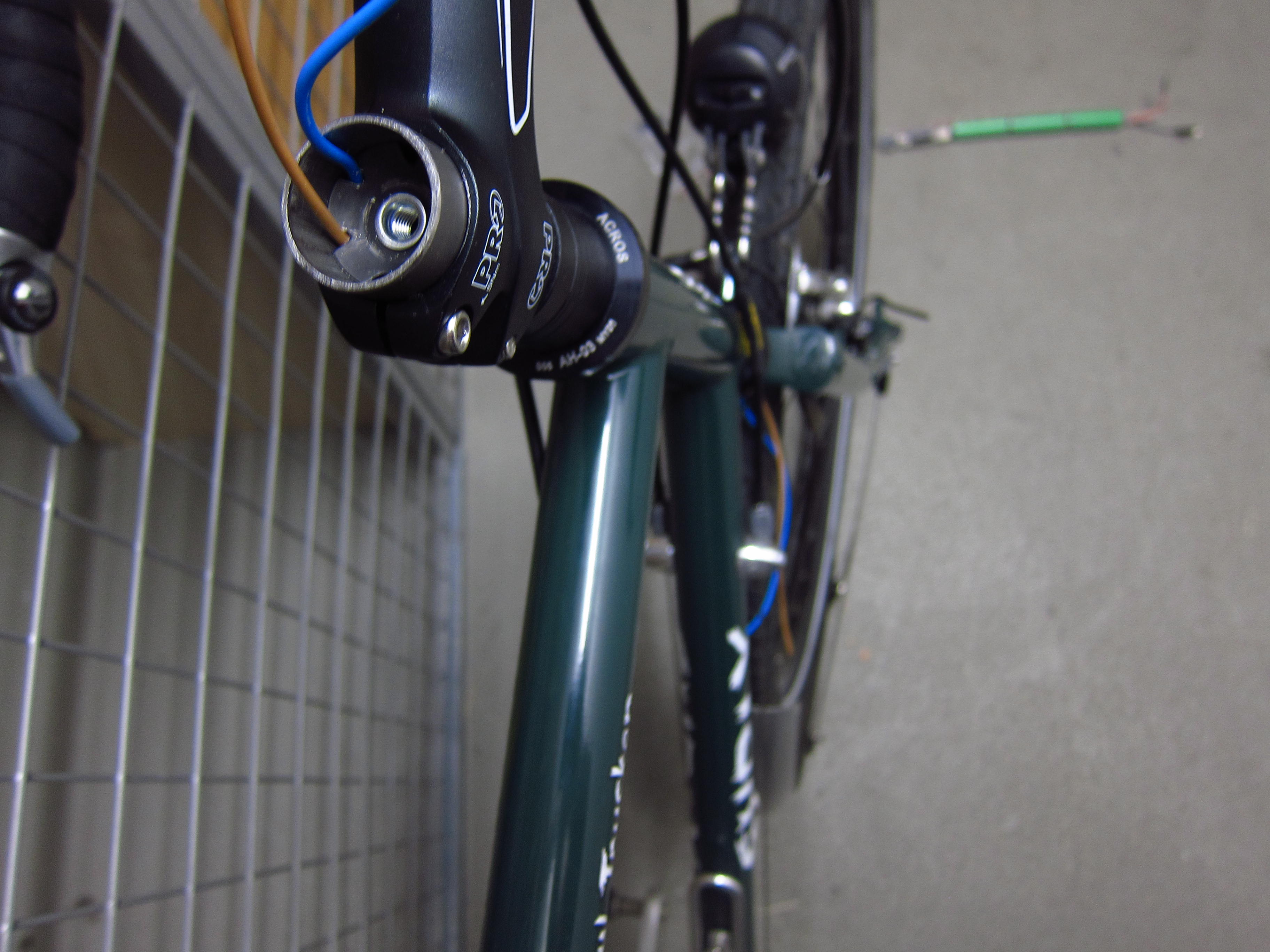
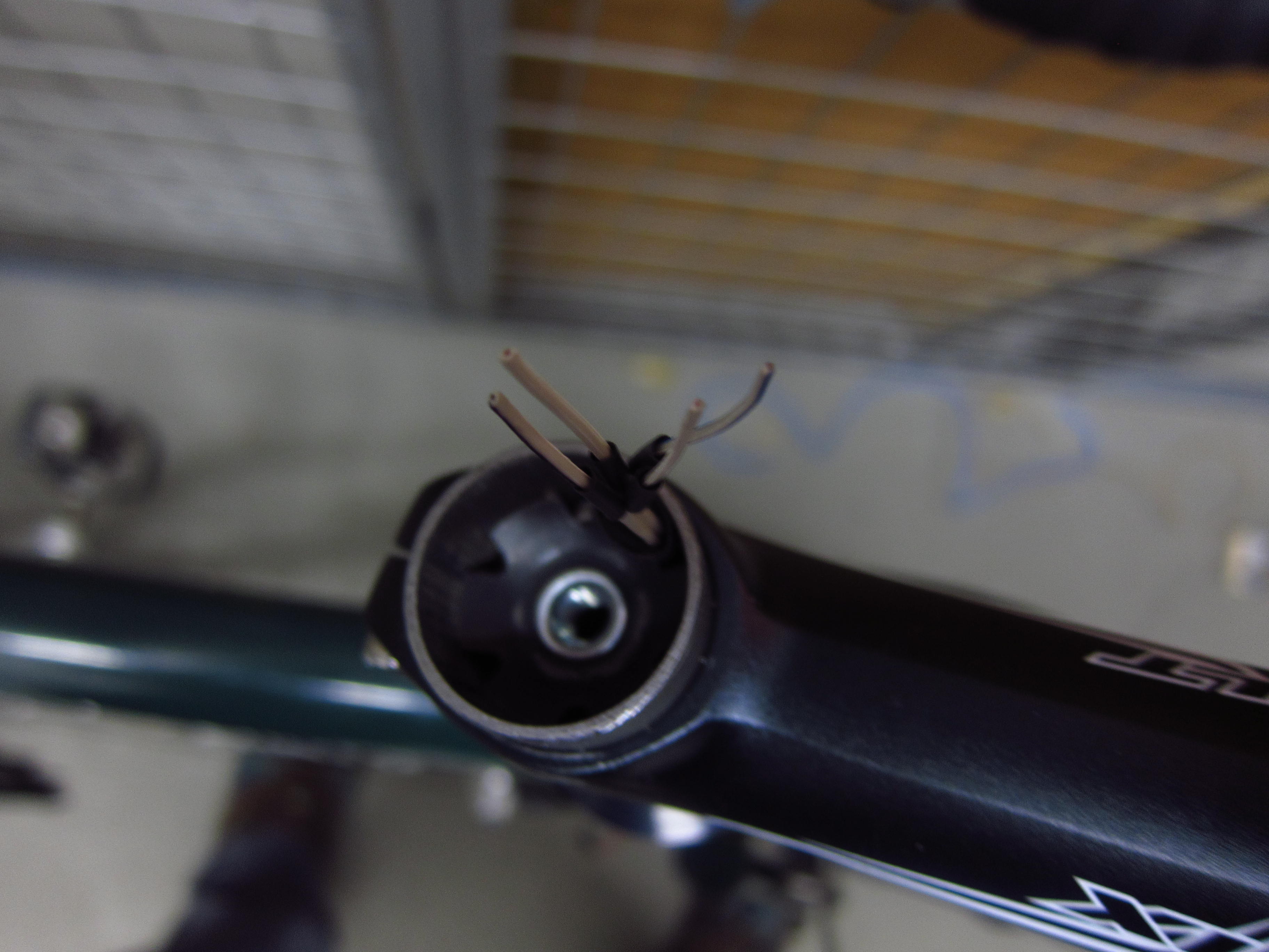
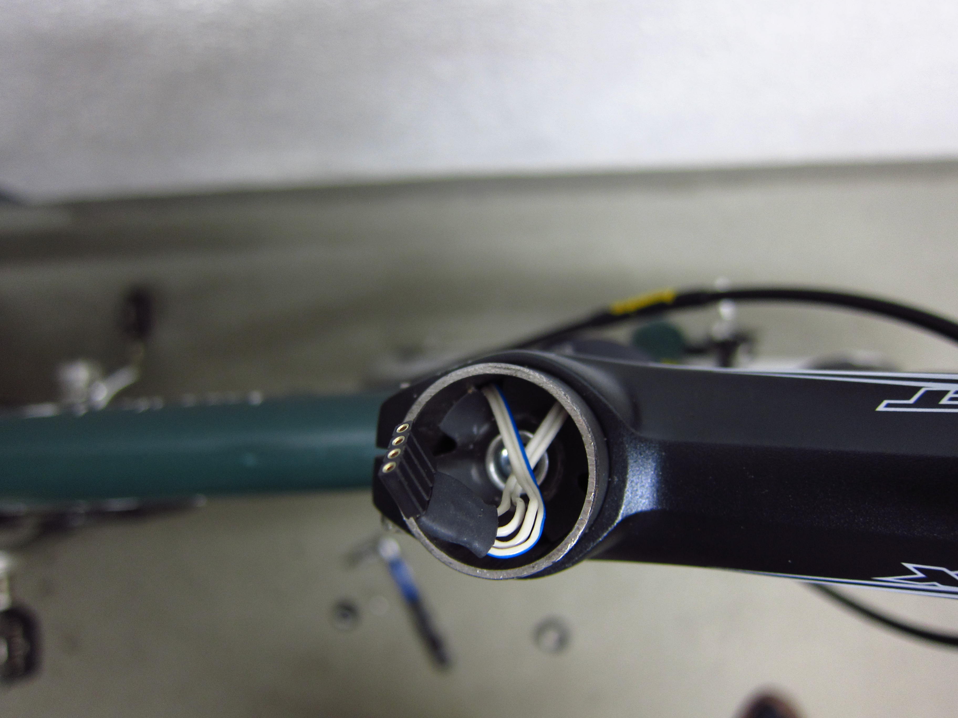
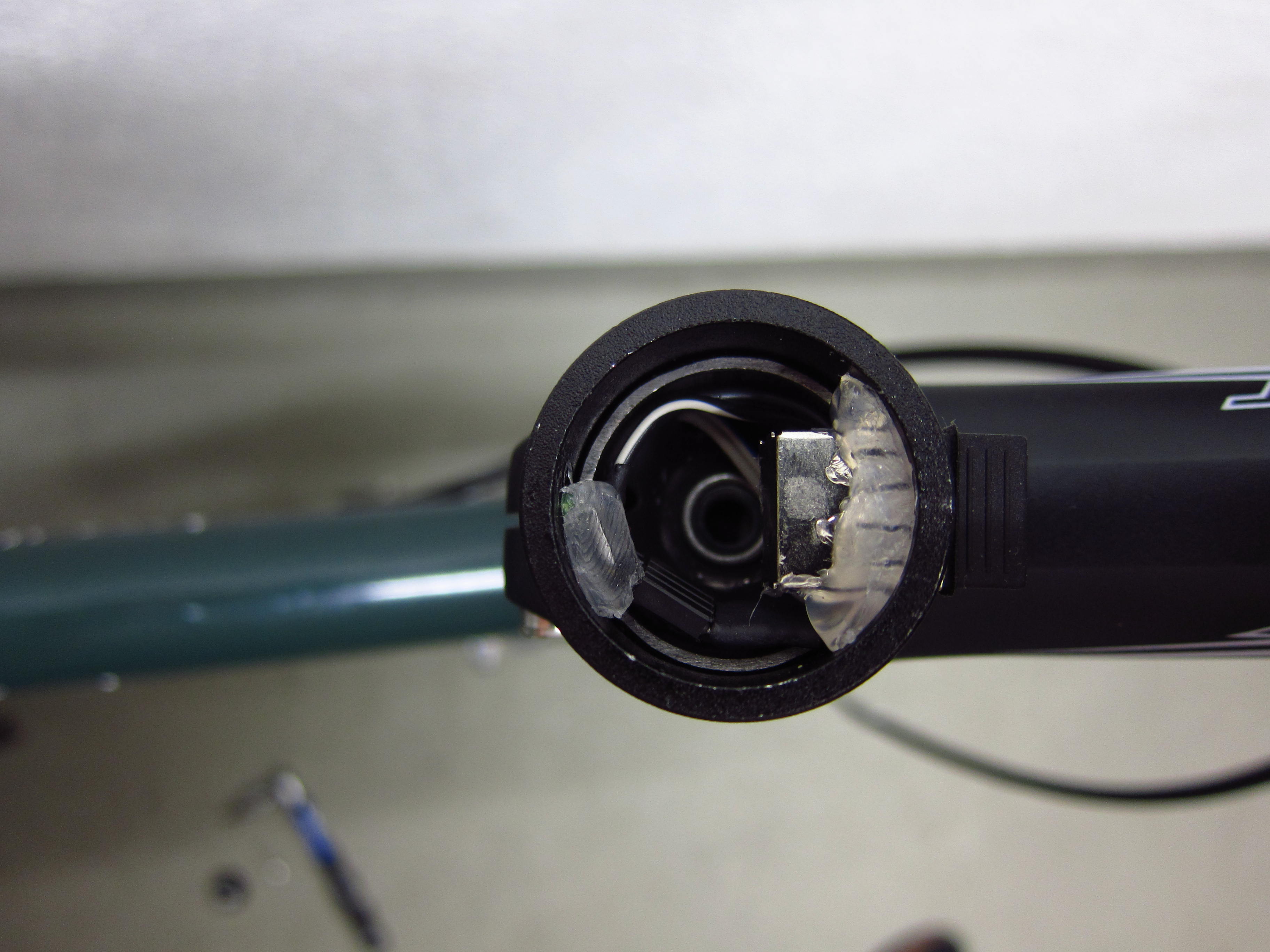
The plugs will finally arrive at the cavity of the stem.

20131024_Scott-Plasma-TT_47

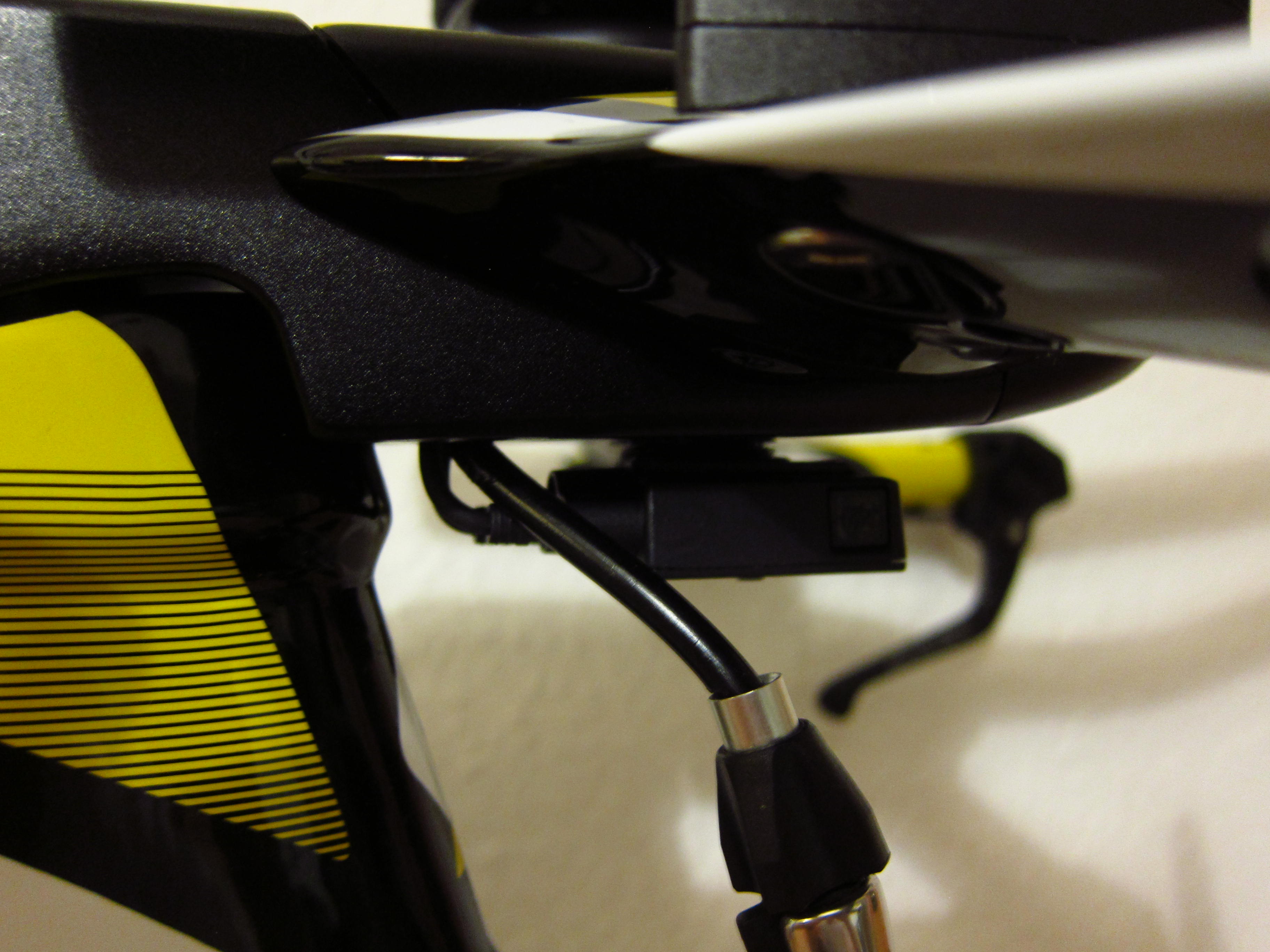
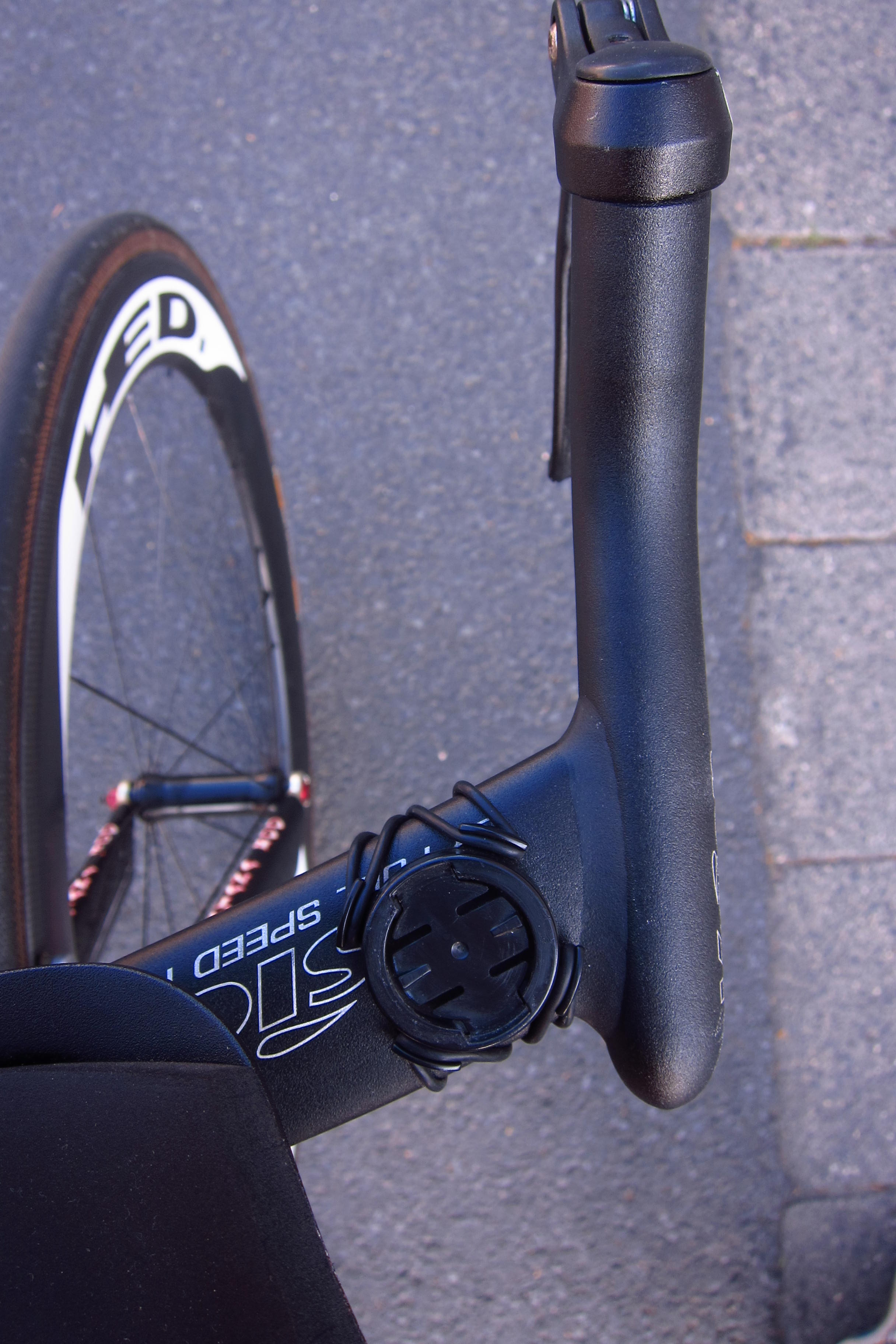
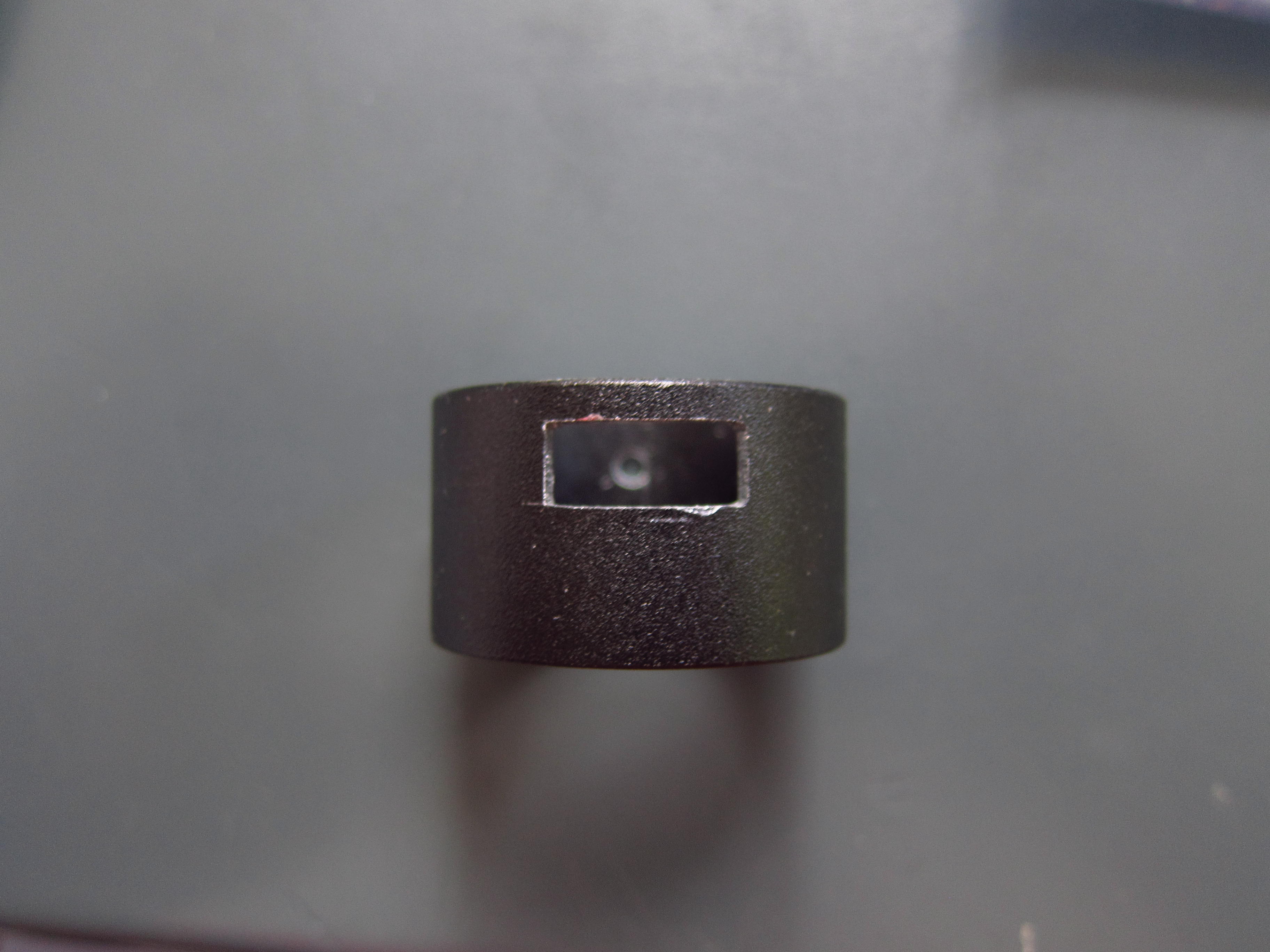
The original plan was to put the front junction box into the cavity.

20131024_Scott-Plasma-TT_471

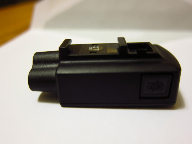
Despite grinding off some plastic extensions of the front junction, I wasn’t successful to achieve that – the box is a couple of millimeters to long.

20131024_Scott-Plasma-TT_472

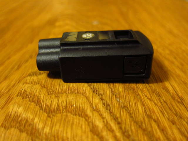
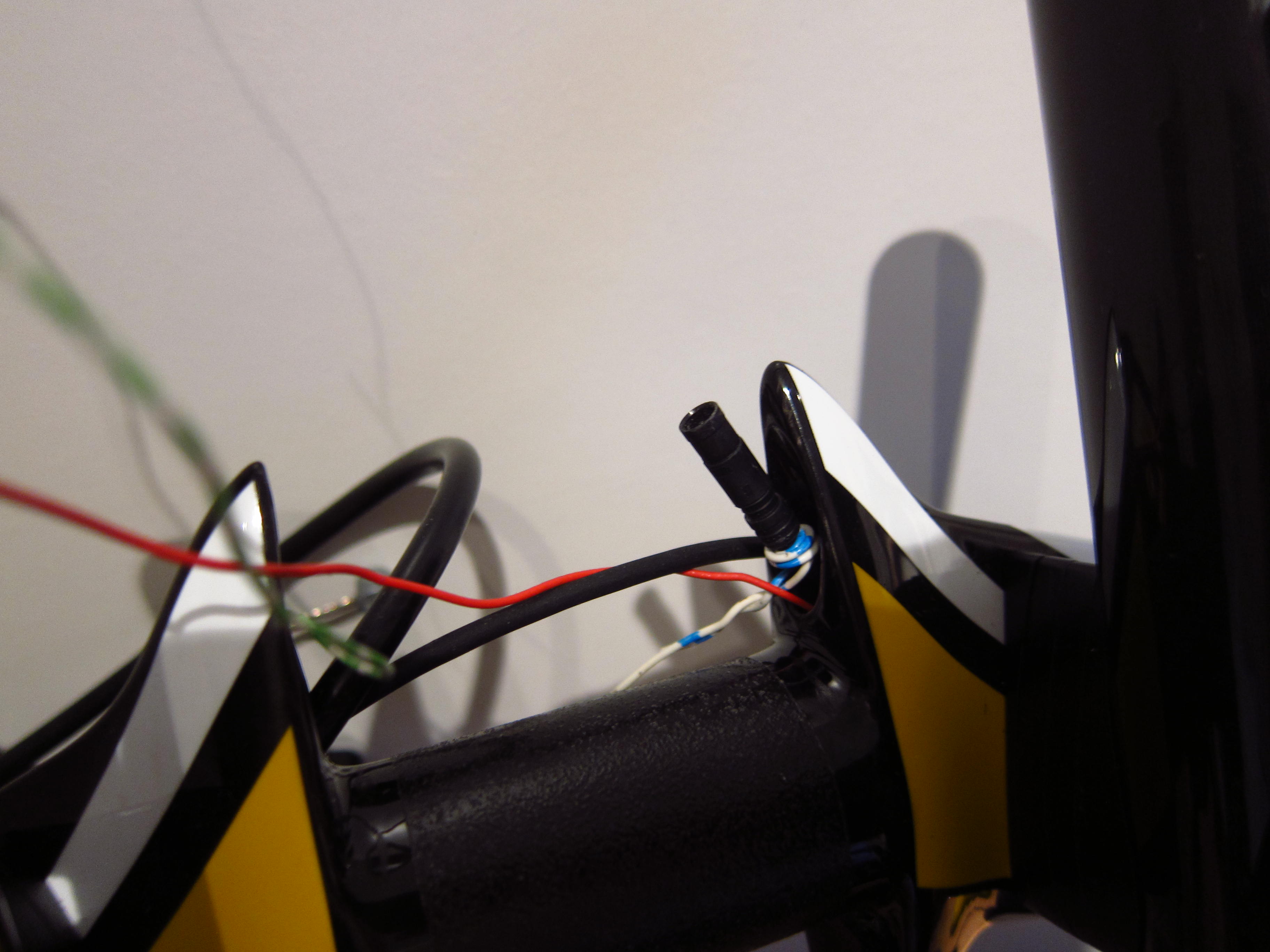
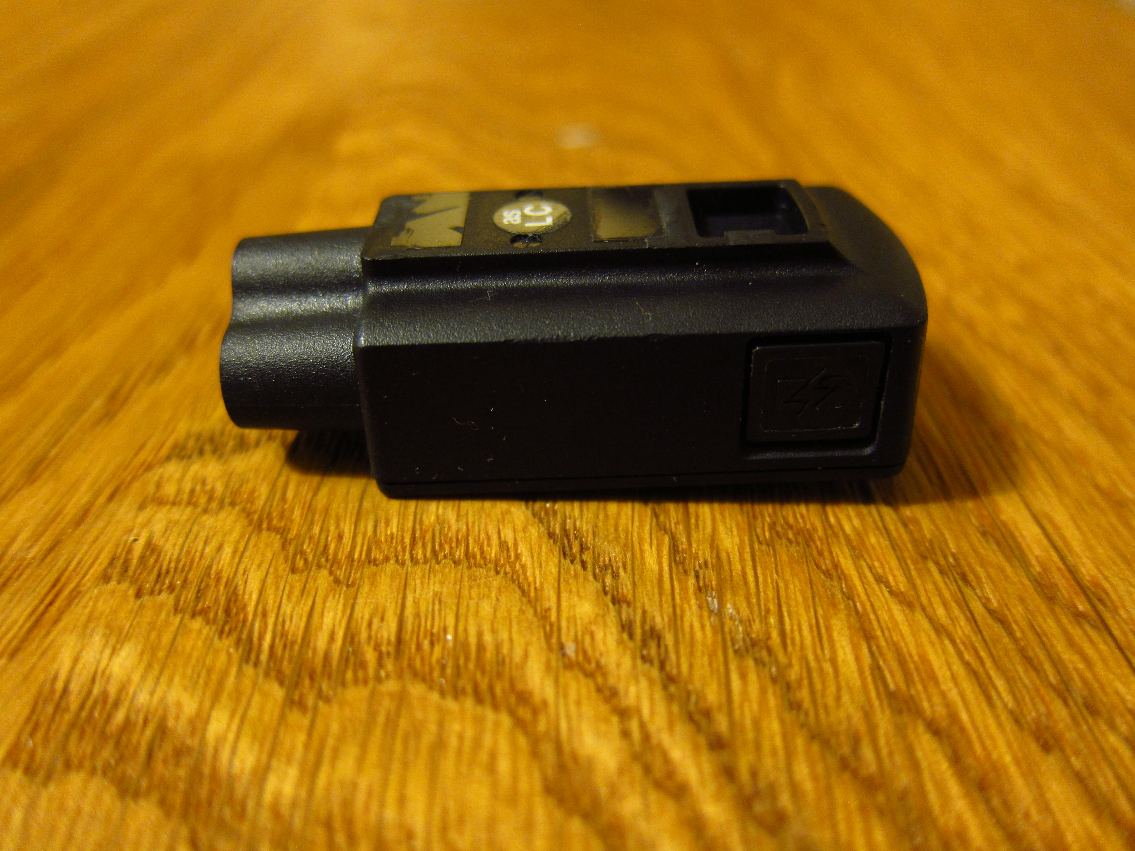
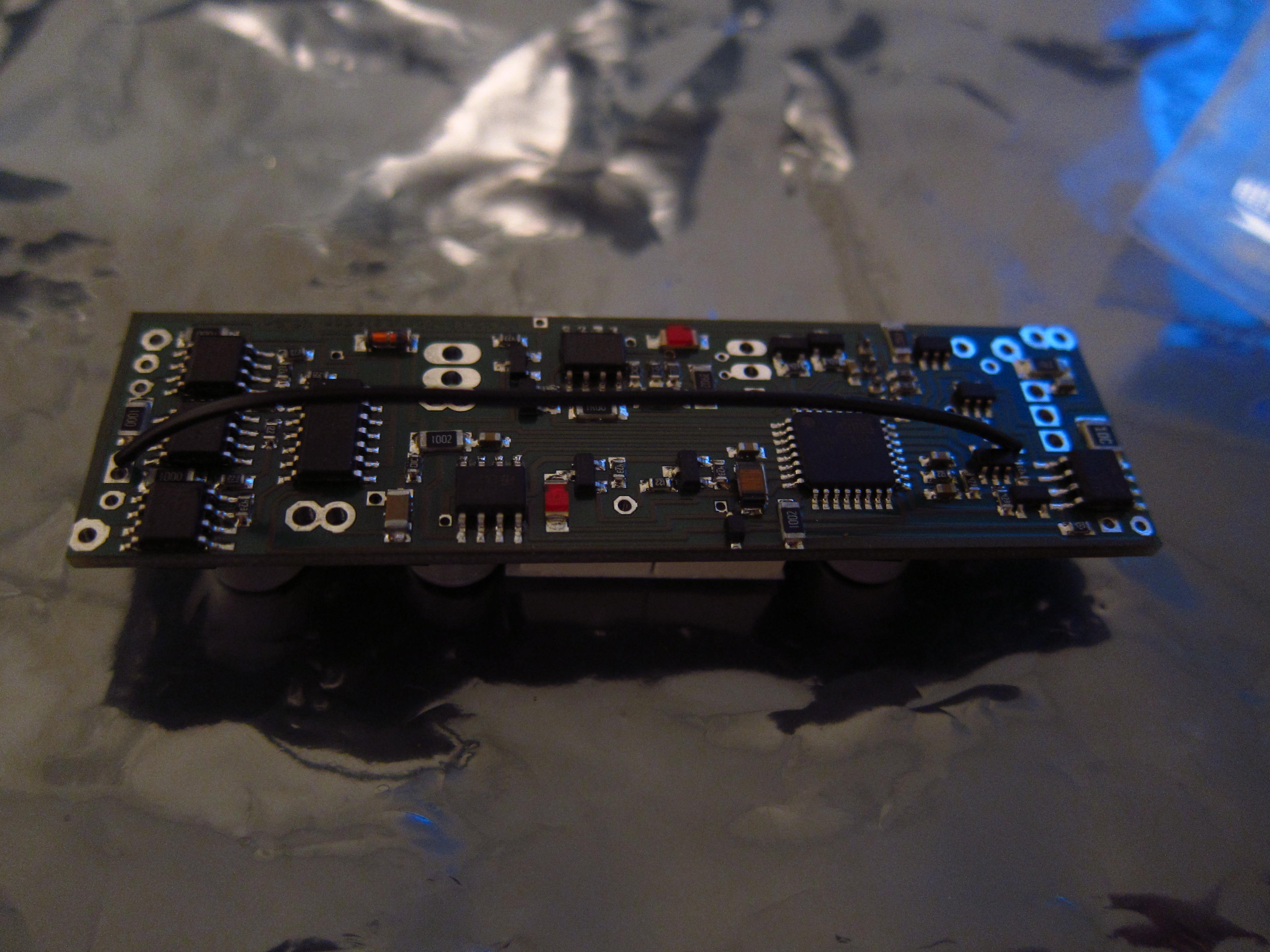
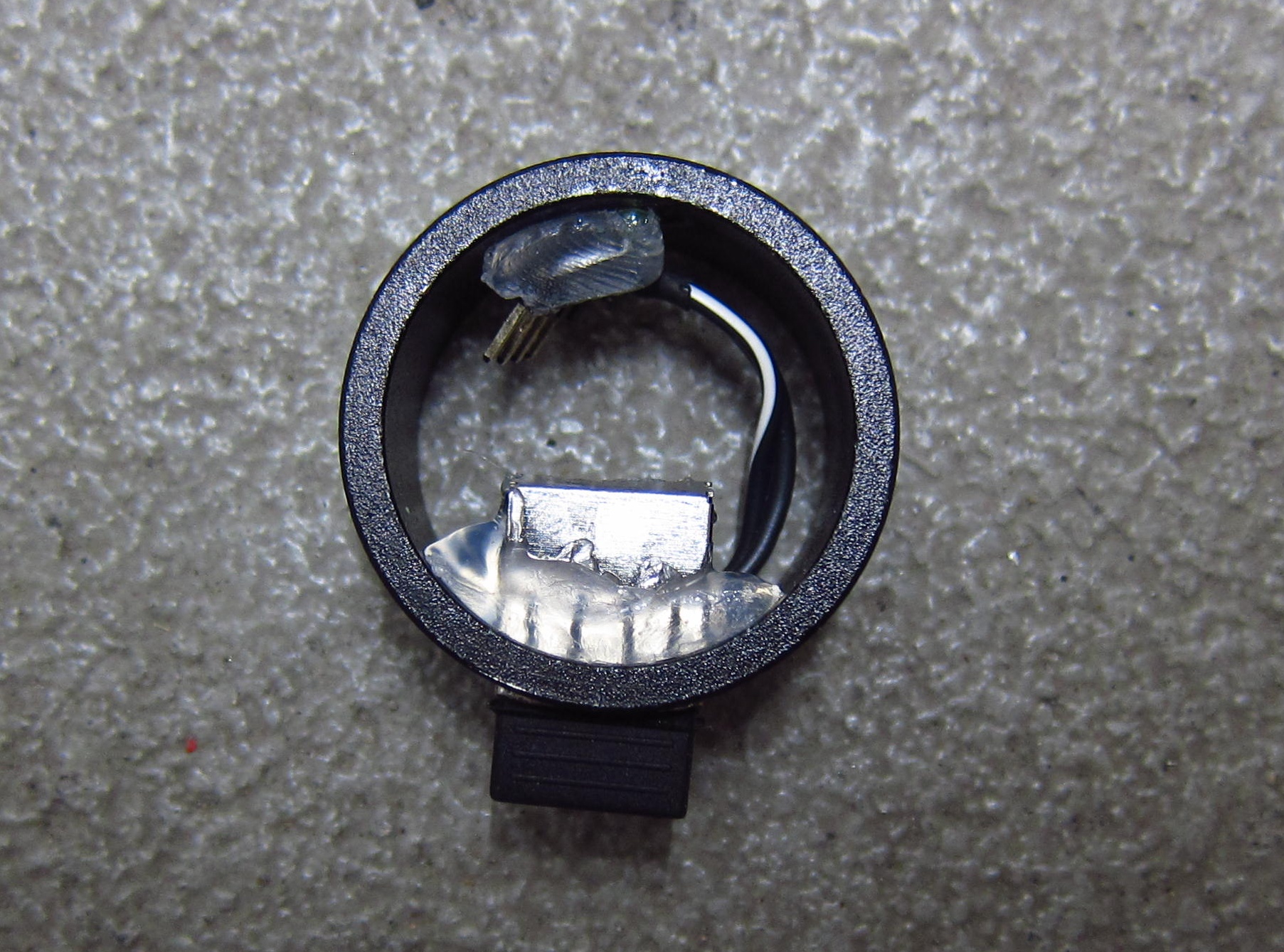
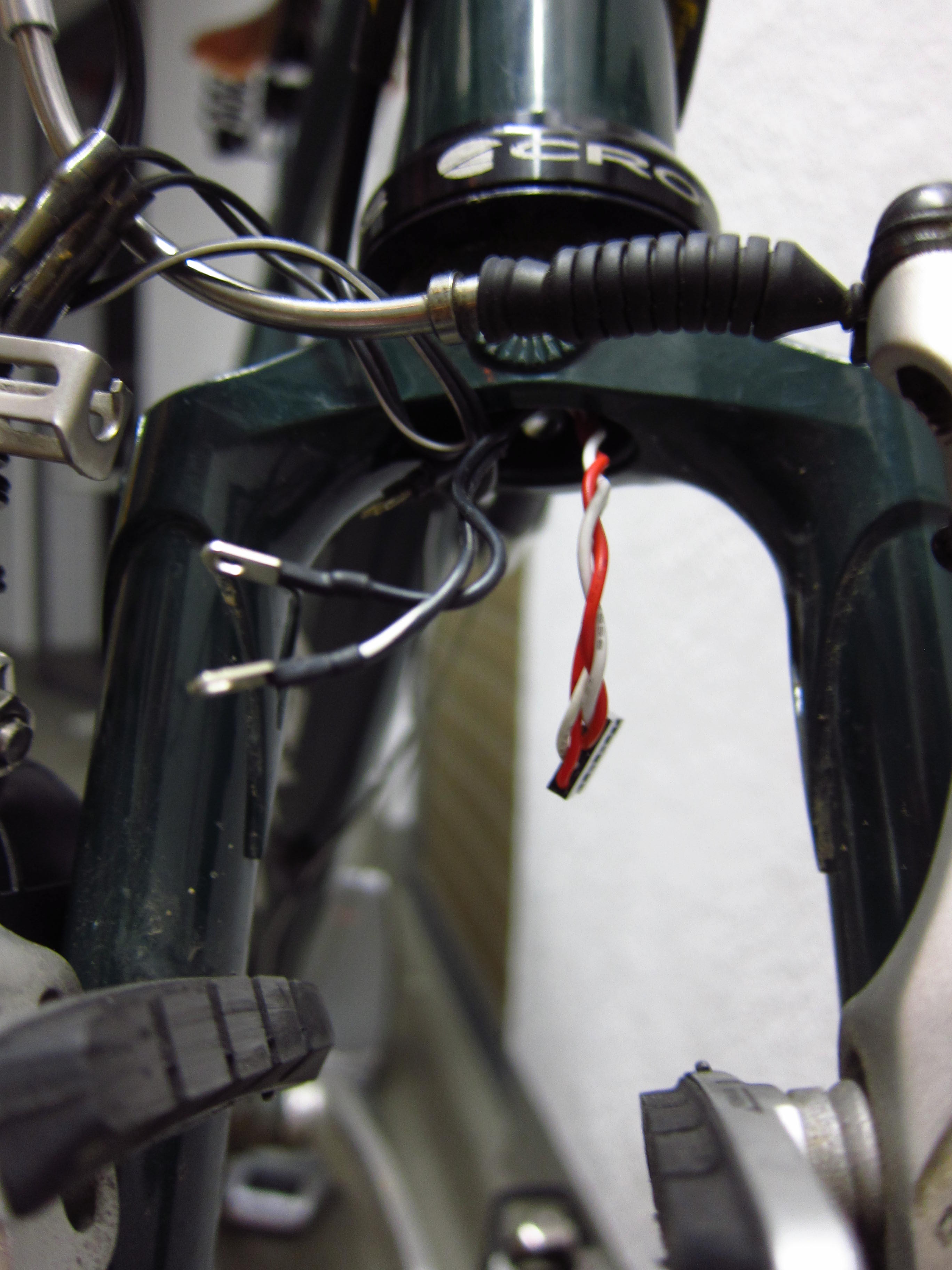
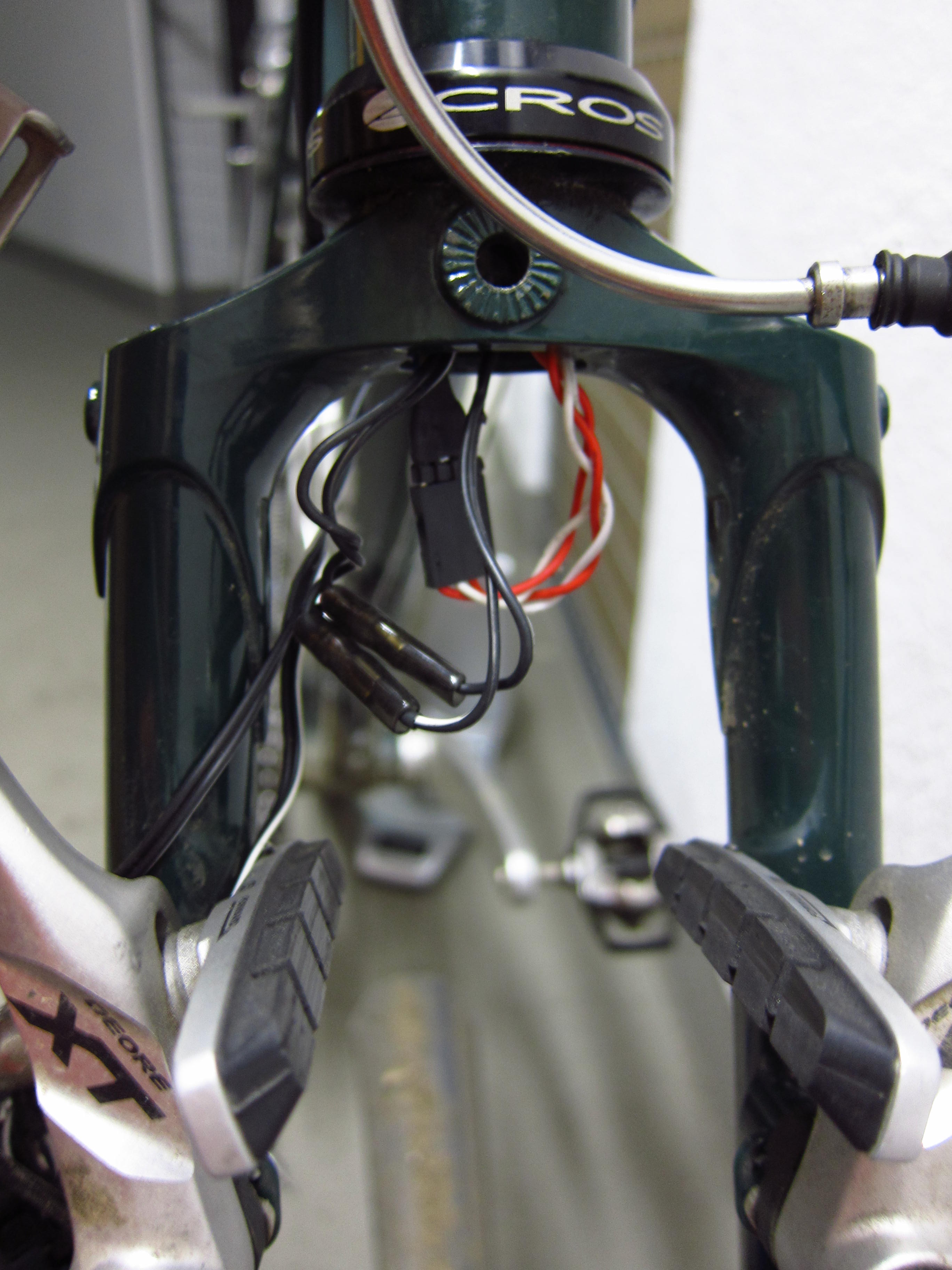
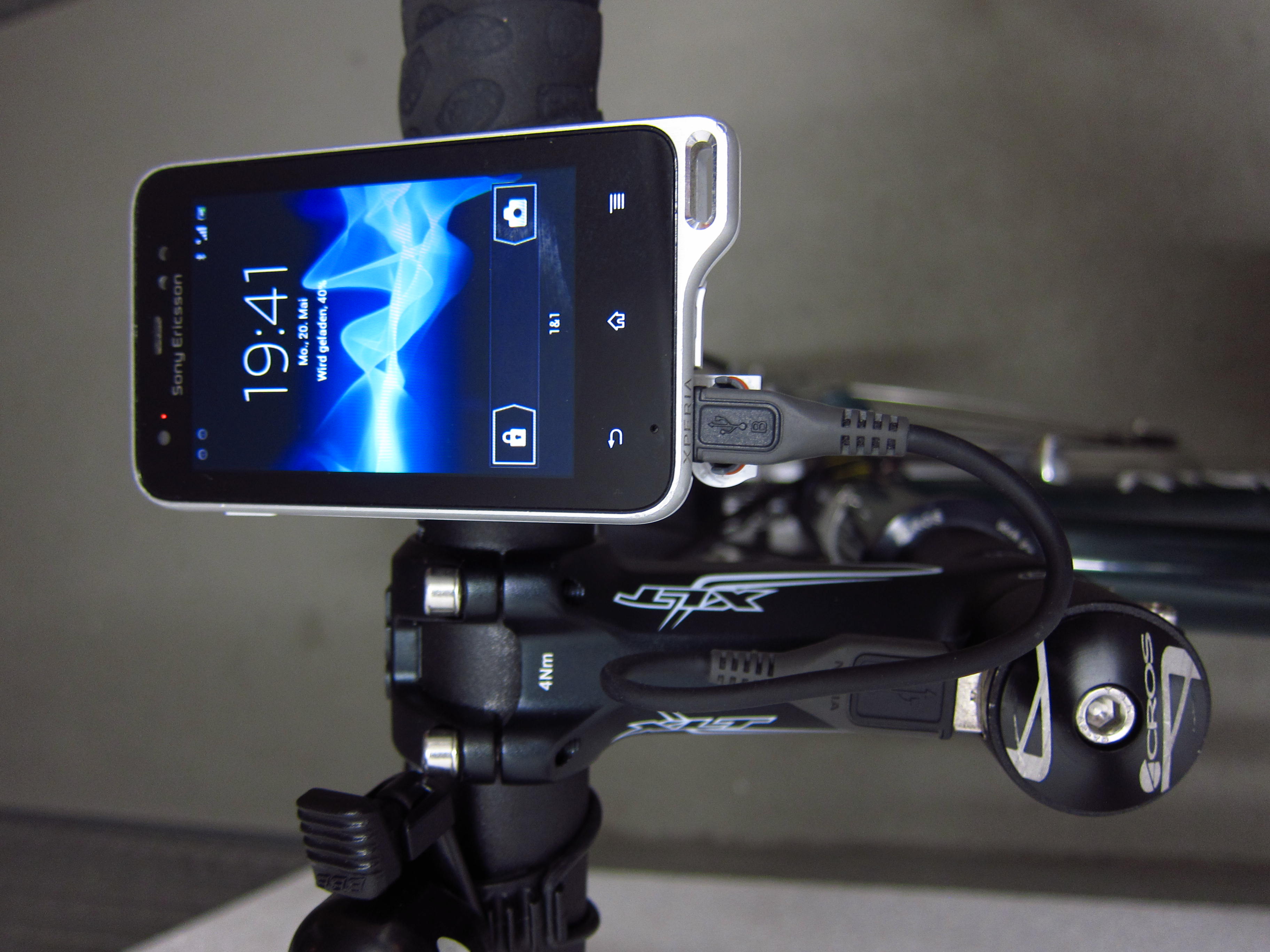
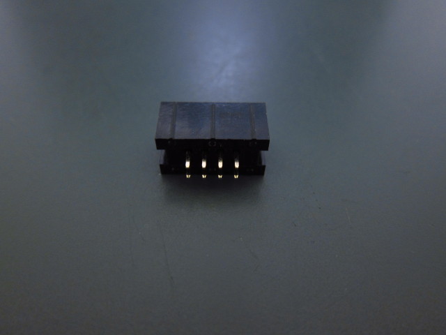
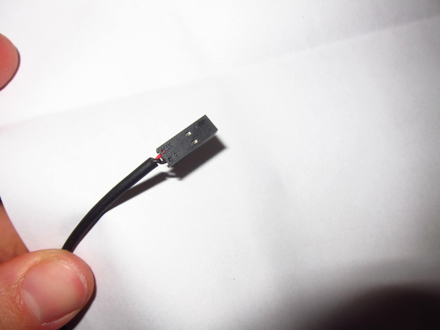
So I decided to mount the front junction directly beneath the stem and to merge all Di2 wires by a custom junction box within the stem – as a result, only one shifter cable will leave the stem.

20131024_Scott-Plasma-TT_473

20131024_Scott-Plasma-TT_474

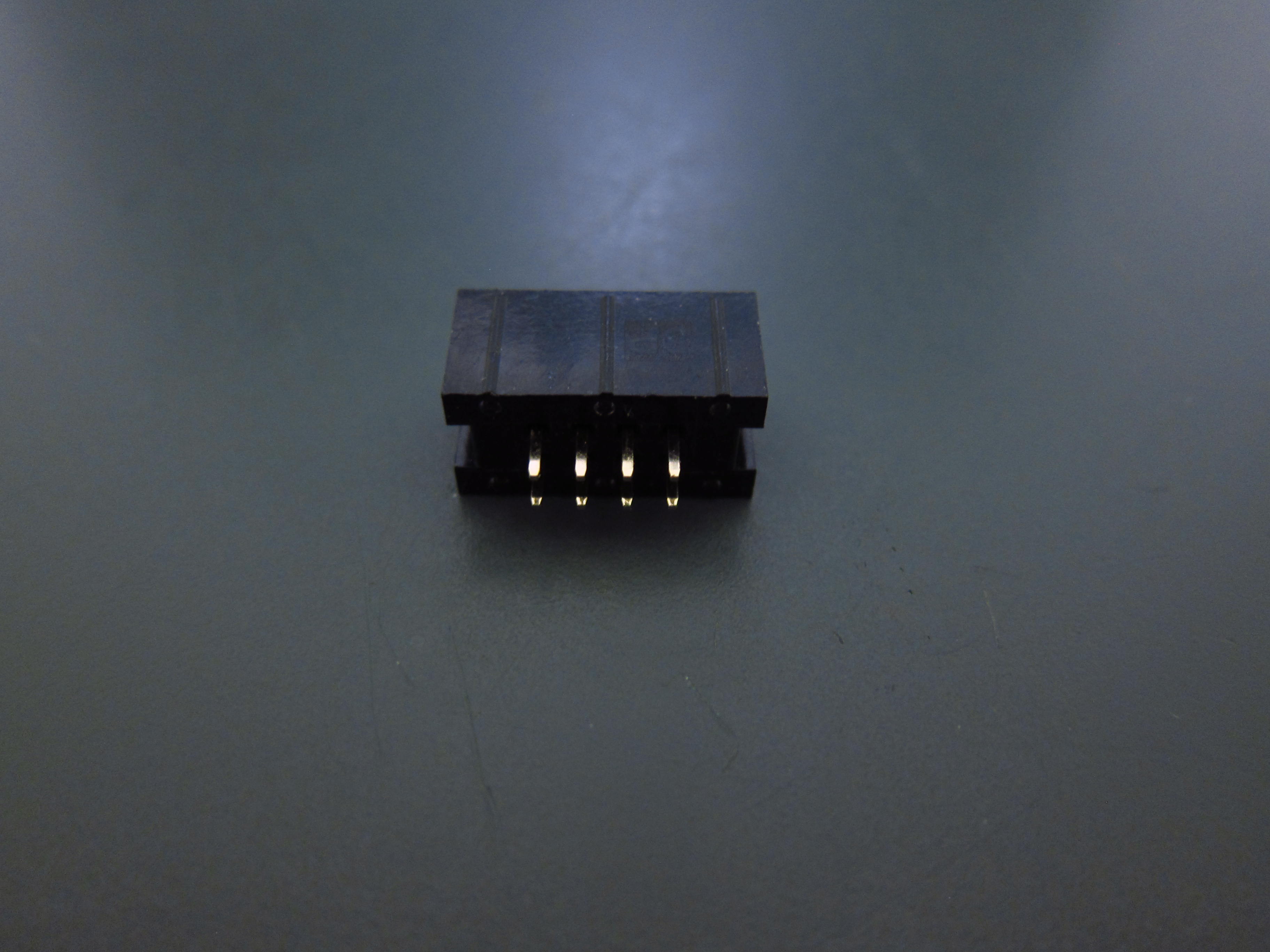
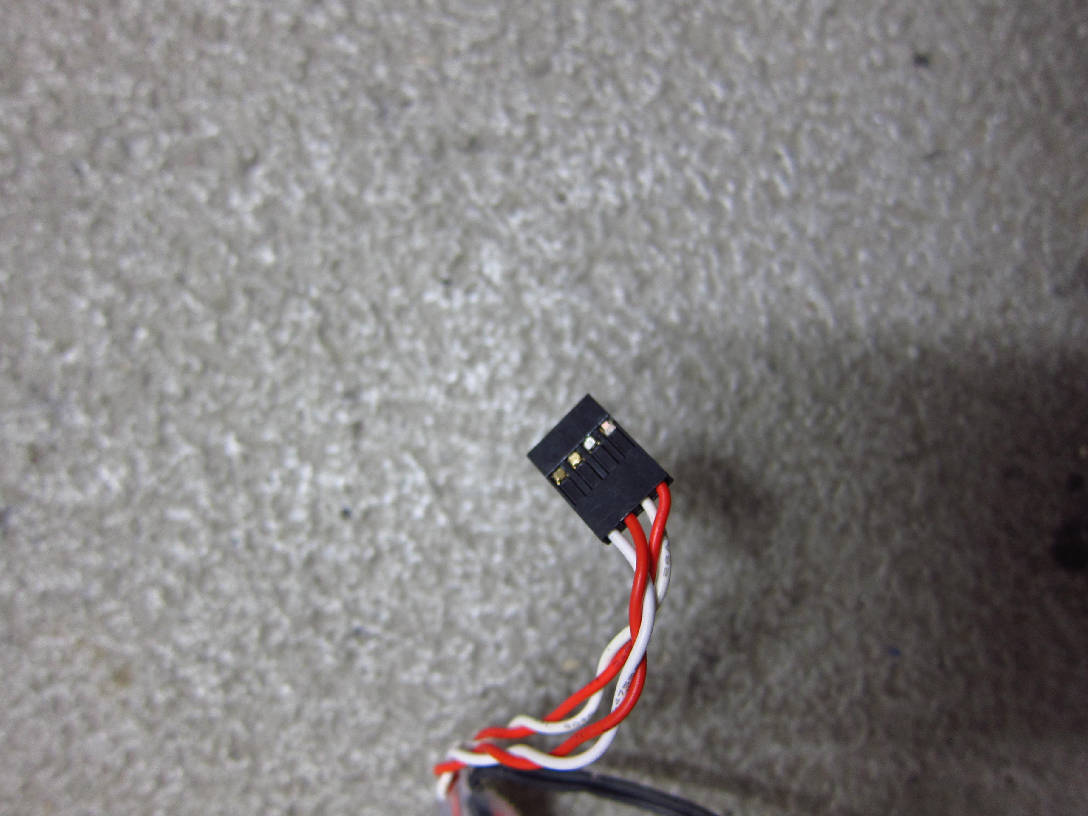
This custom junction box is based on a plug most commonly used on PC mainboards.

20131024_Scott-Plasma-TT_50

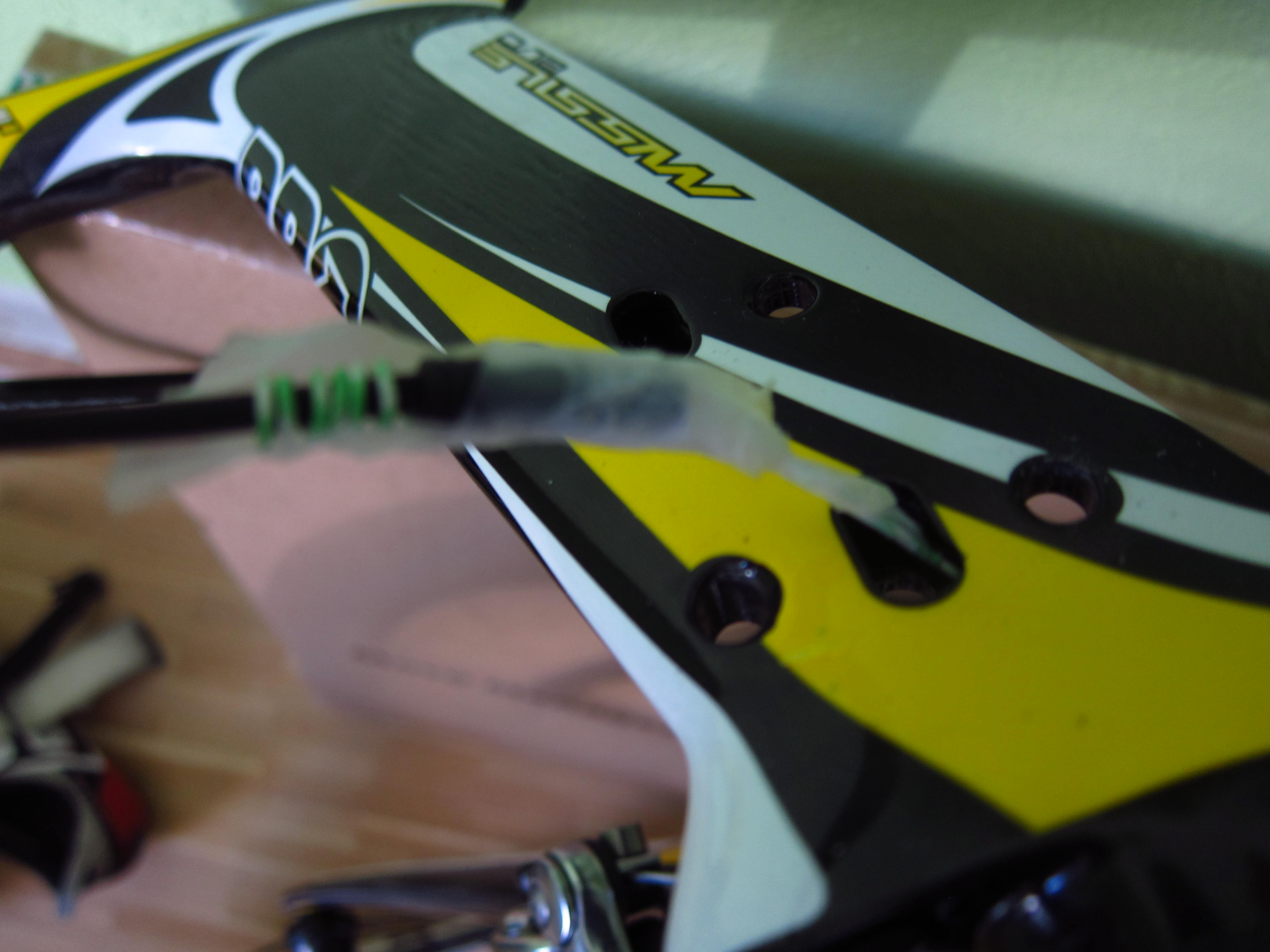
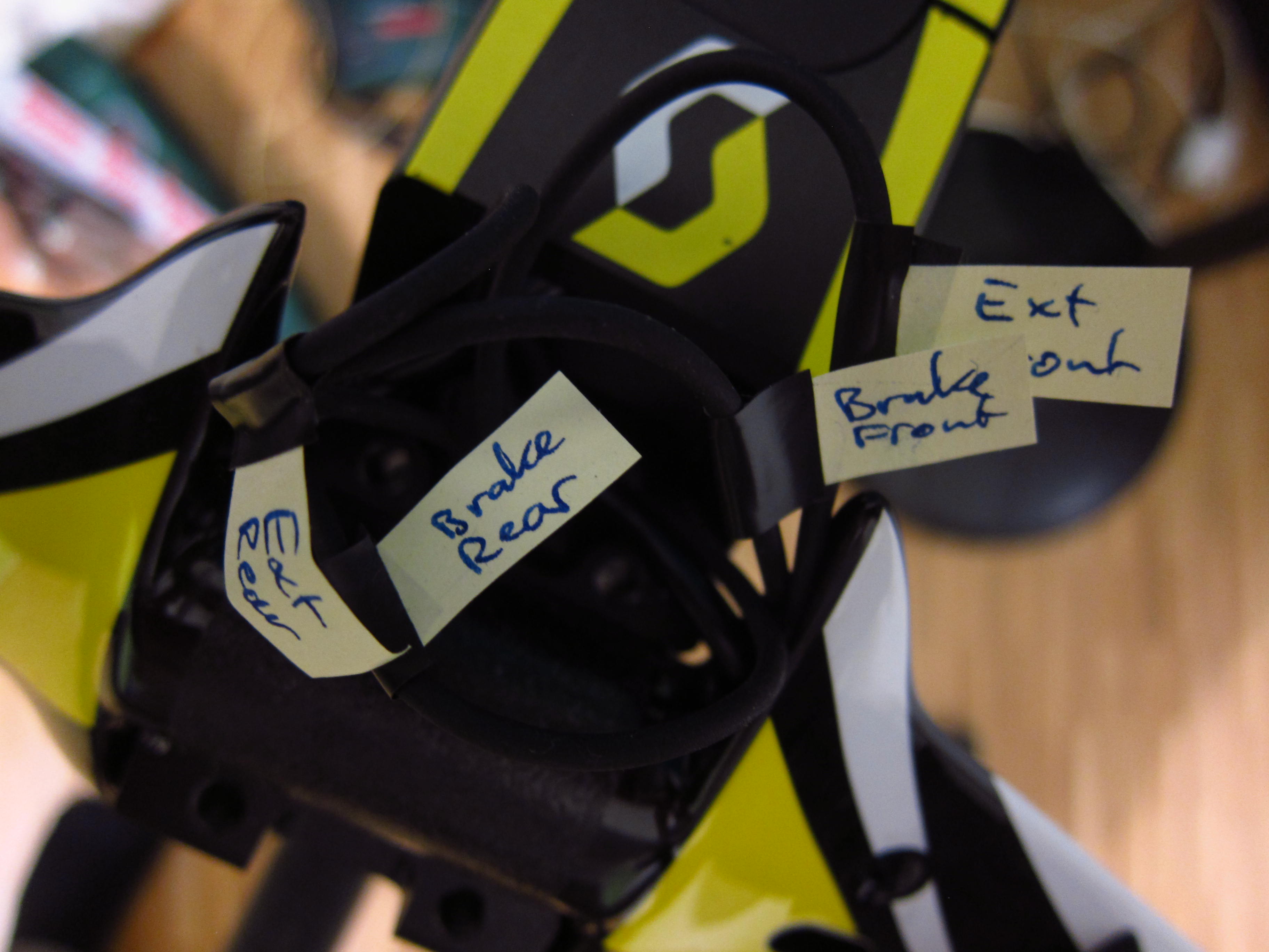
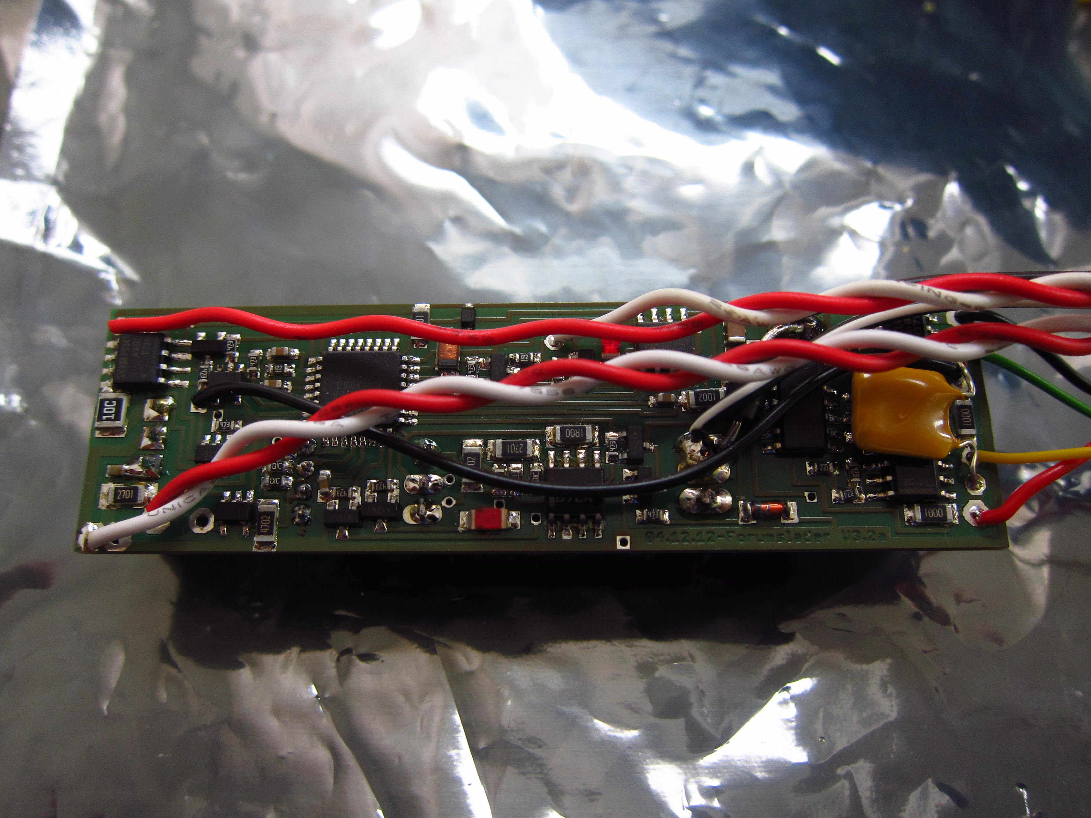
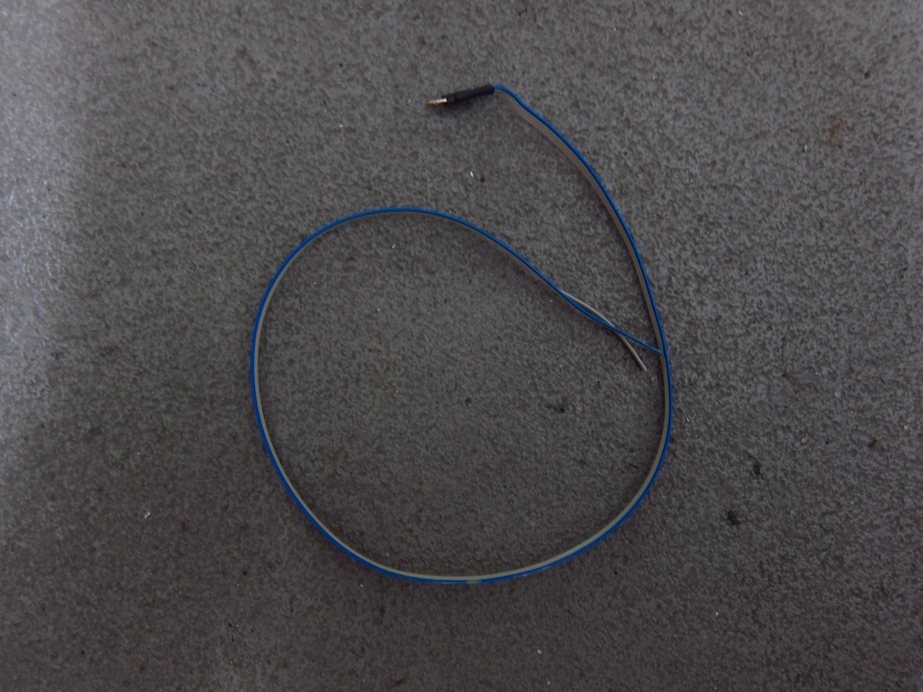
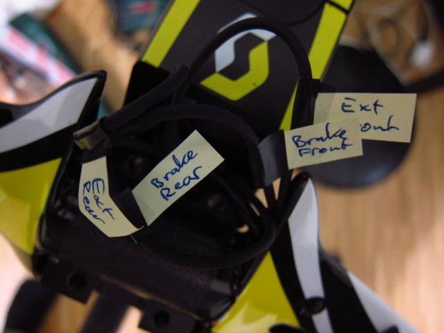
Before cutting of the original Shimano plugs, I labeled all cables.

20131024_Scott-Plasma-TT_53

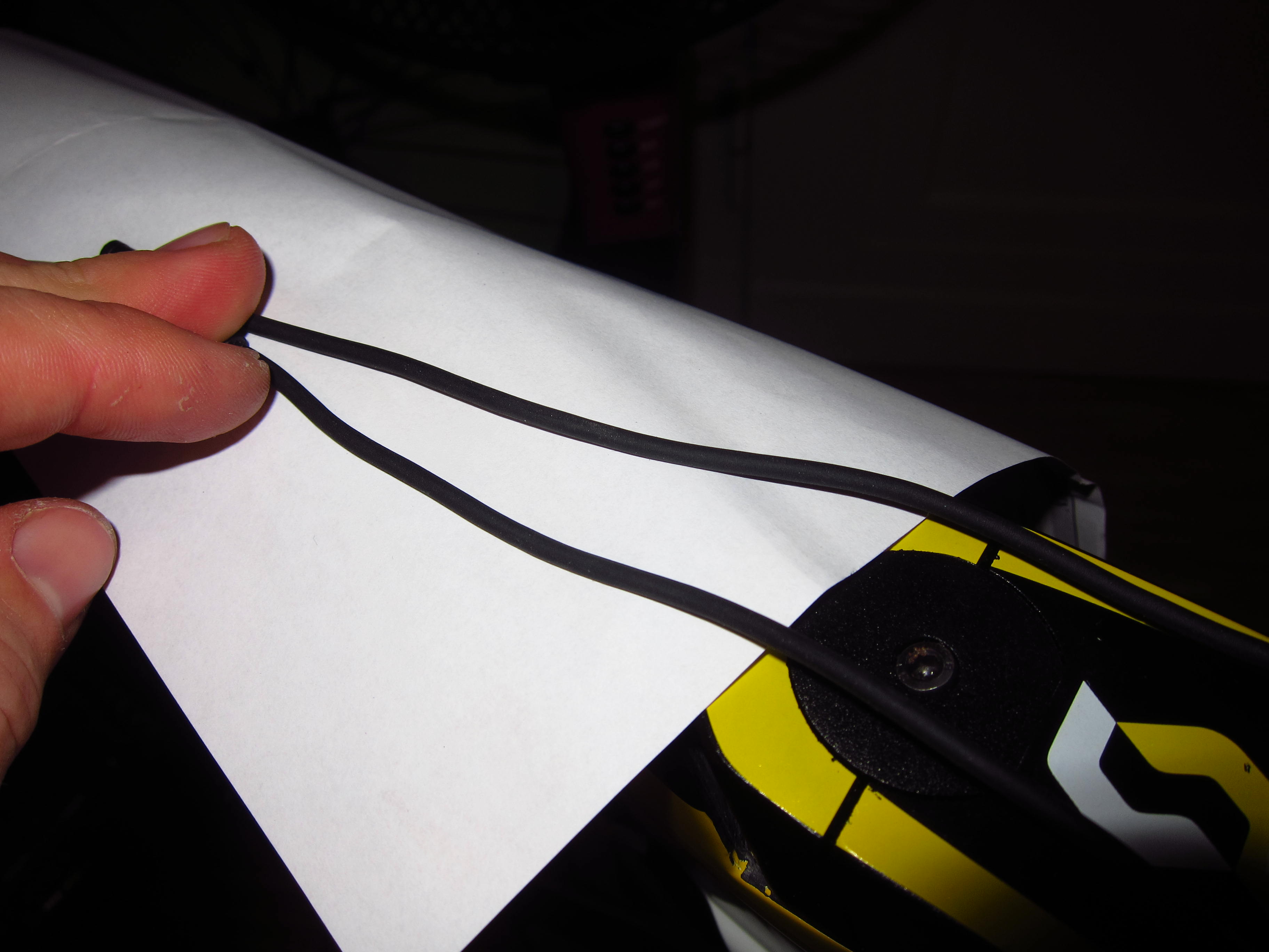
After that, I determined the necessary remaining cable length…
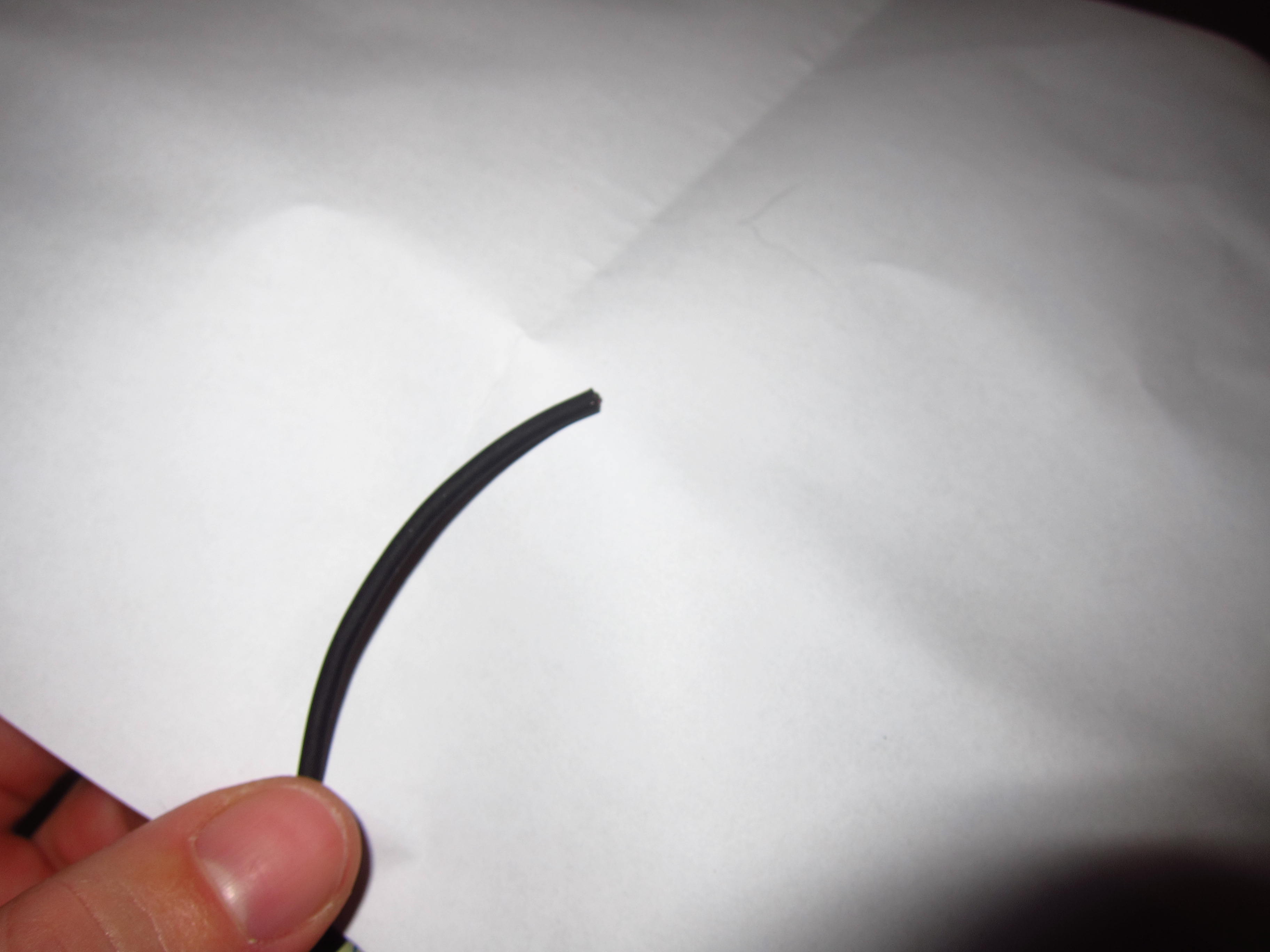
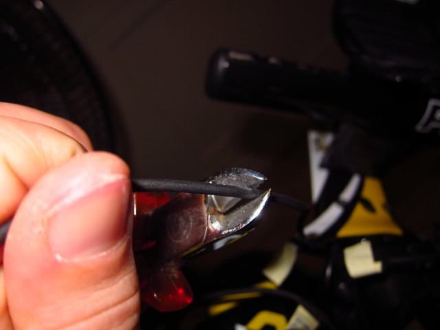
20131024_Scott-Plasma-TT_54

and made the cuts.

20131024_Scott-Plasma-TT_55

20131024_Scott-Plasma-TT_56

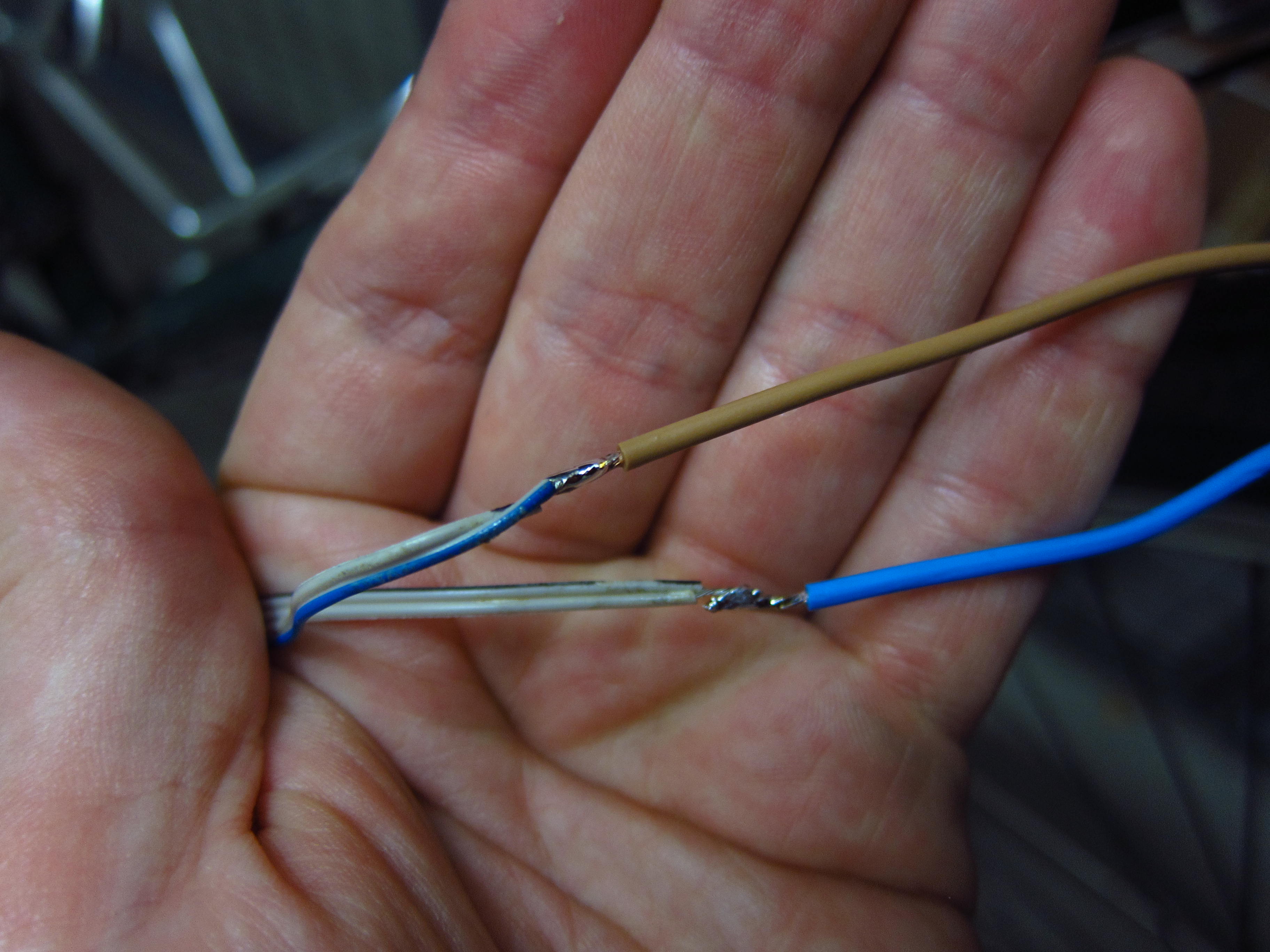
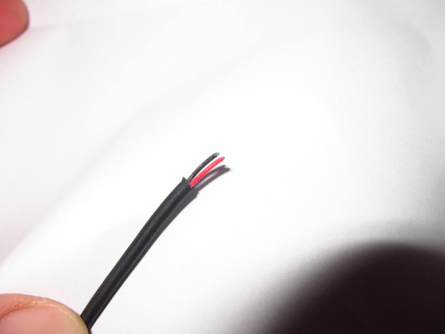
The newer Shimano electronic shifting gruppos use a so called “eTube platform” which is, from an engineering perspective, a CAN bus system. This system utilizes only two wires for both power supply and signal transmission. So it wasn’t a surprise to find only two wires after removing the insulation.

20131024_Scott-Plasma-TT_57

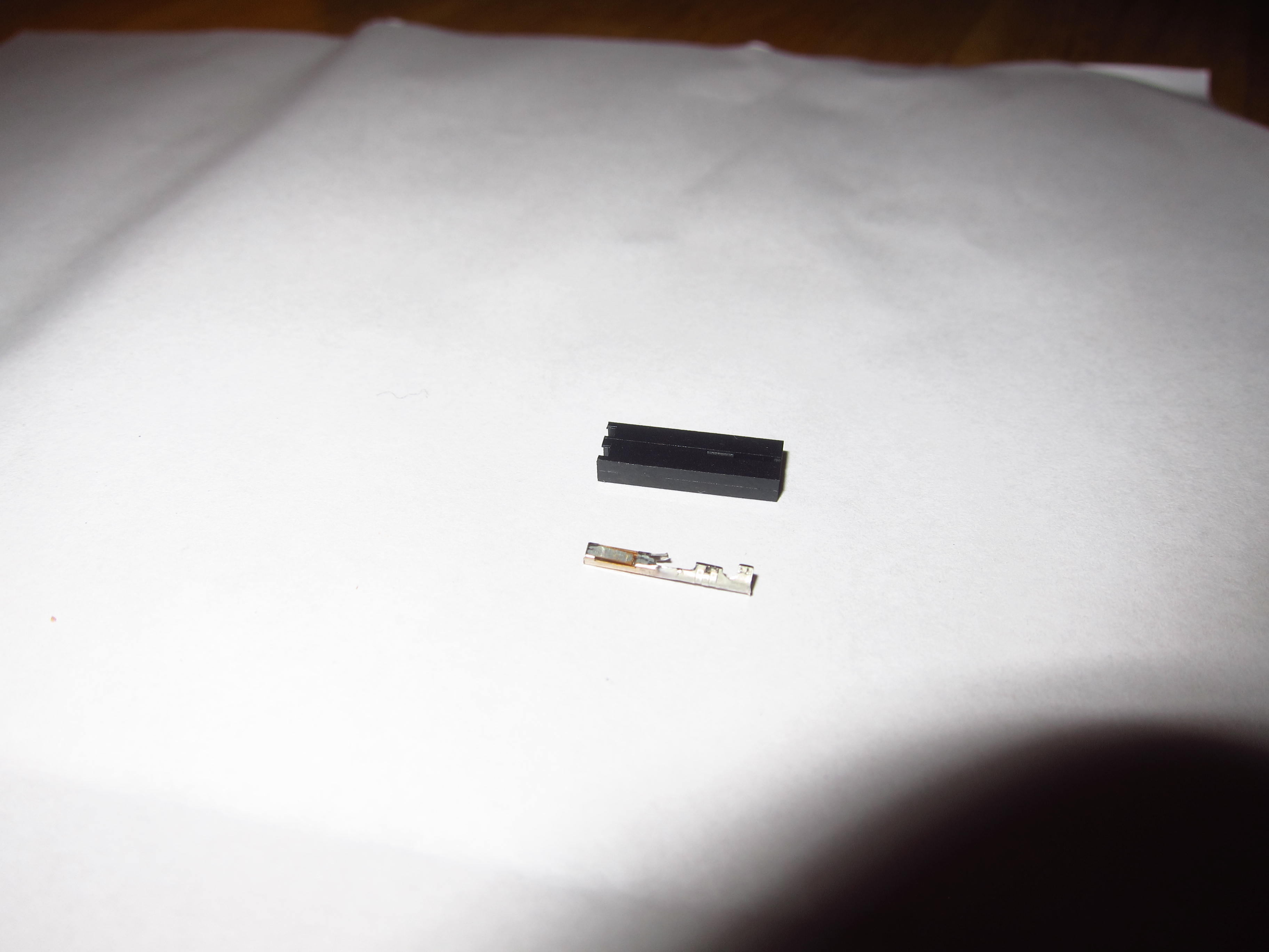
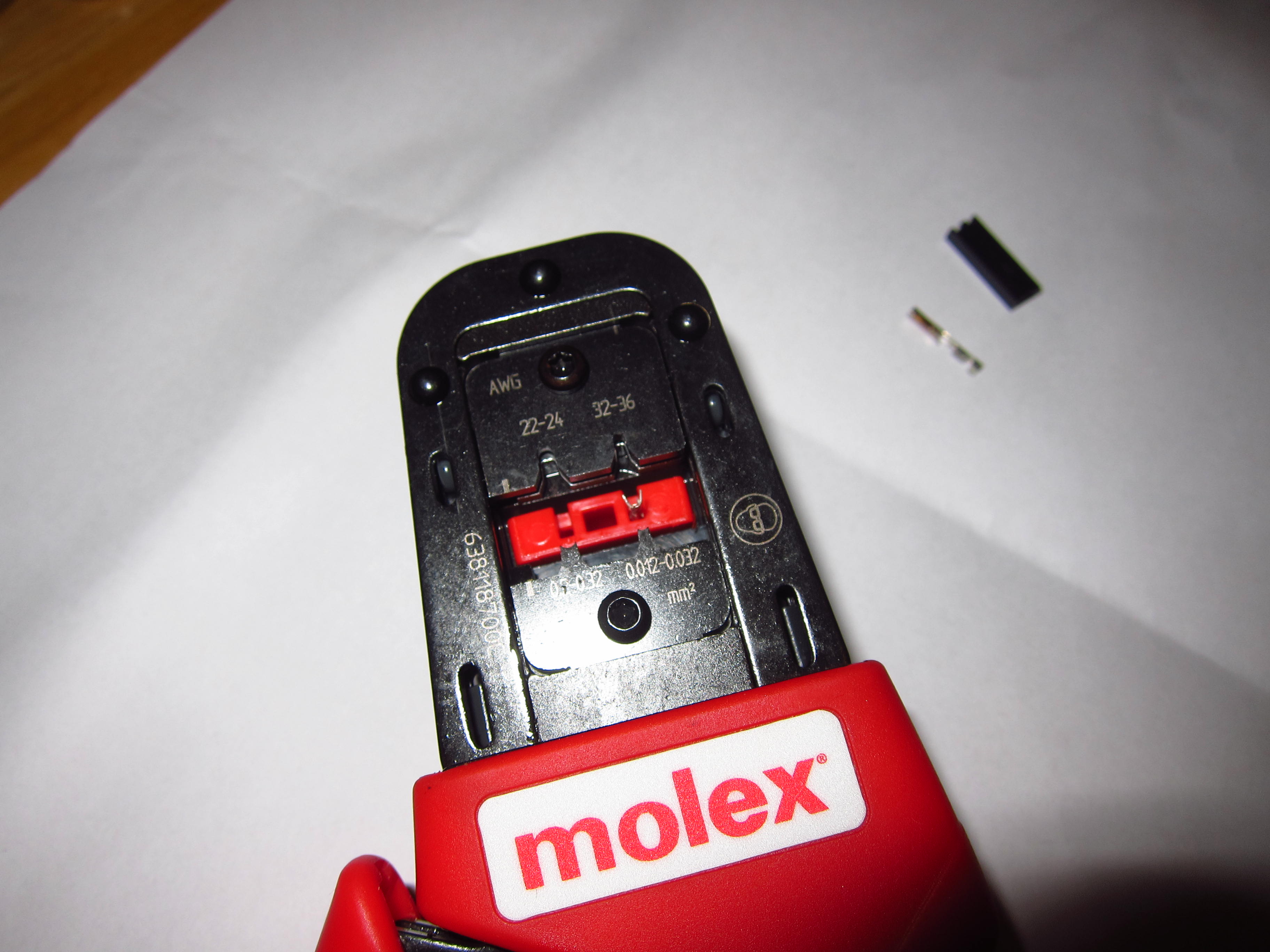
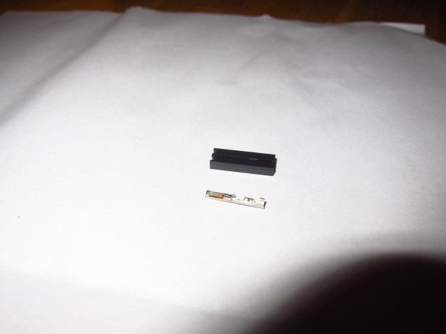
Instead of soldering all red and all black wires together, I opted to use crimp plugs and housings – again, standard PC hardware.

20131024_Scott-Plasma-TT_58

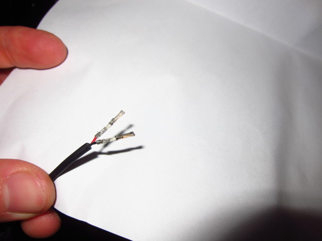
With a proper crimping tool,…

20131024_Scott-Plasma-TT_59

all cable ends looked like this after about ten minutes.

20131024_Scott-Plasma-TT_60

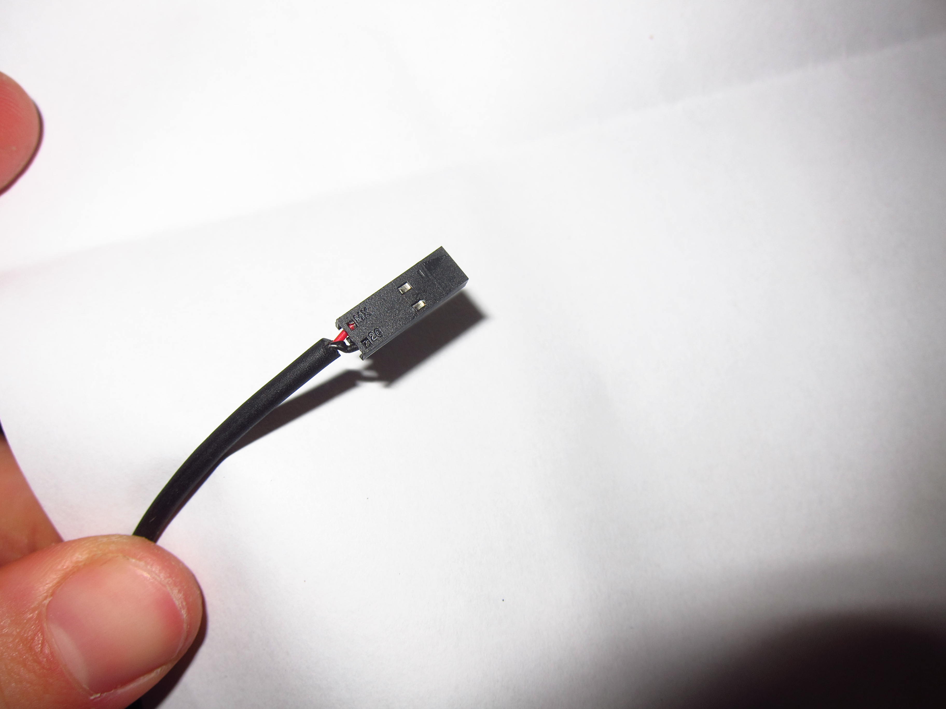
And with the housing installed.

20131024_Scott-Plasma-TT_61

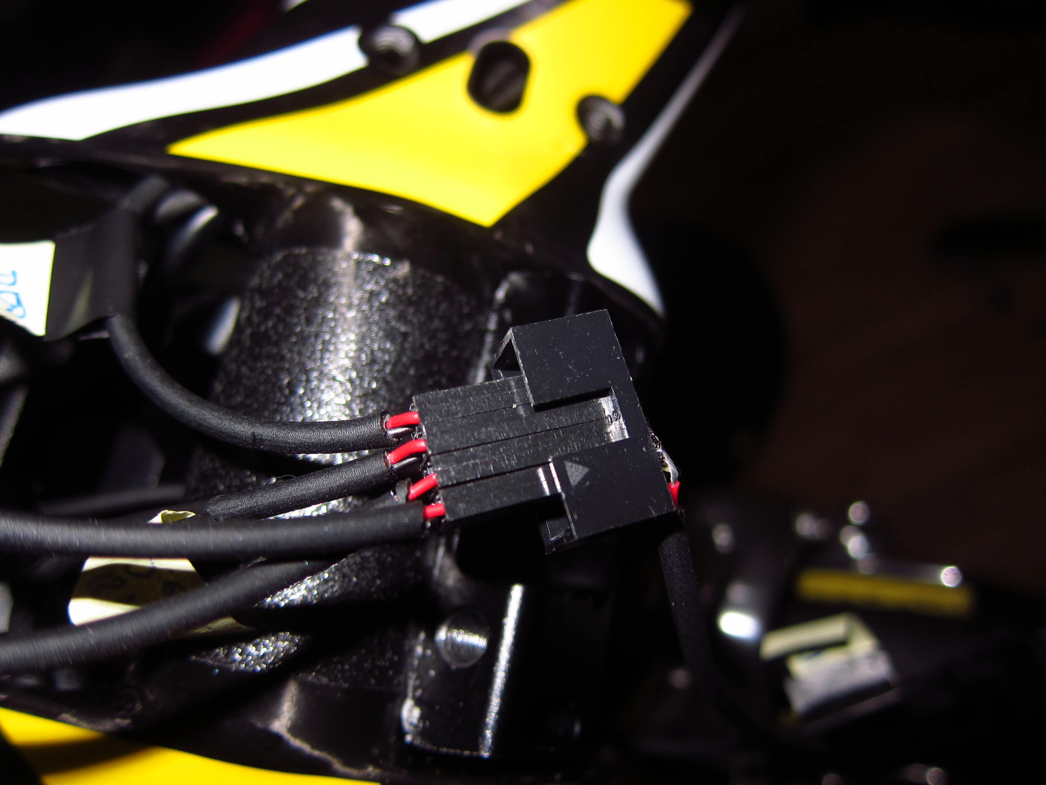
Plugged into the custom “Pre-Junction”.

20131024_Scott-Plasma-TT_62

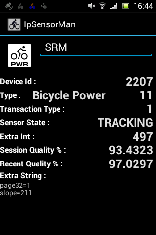
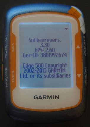
The electronic installation was finalized and everything worked like a charm – however, it requires getting used to charging your bike and installing firmware upgrades ;-).

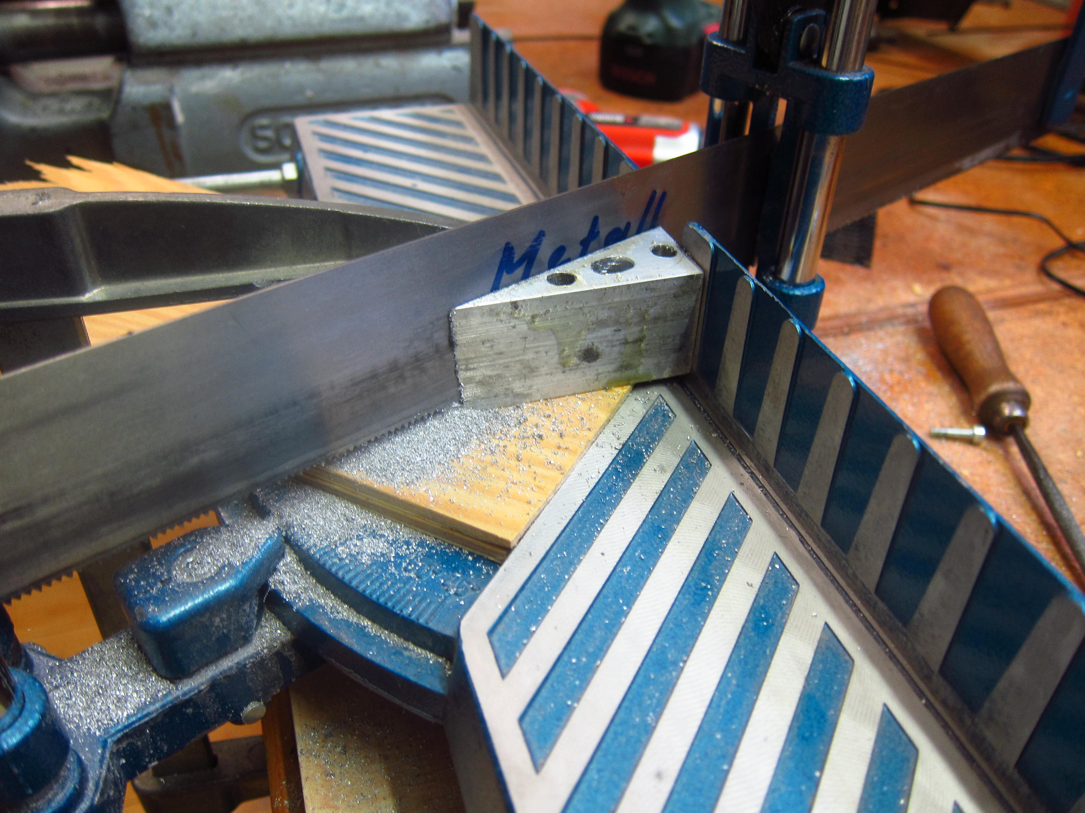
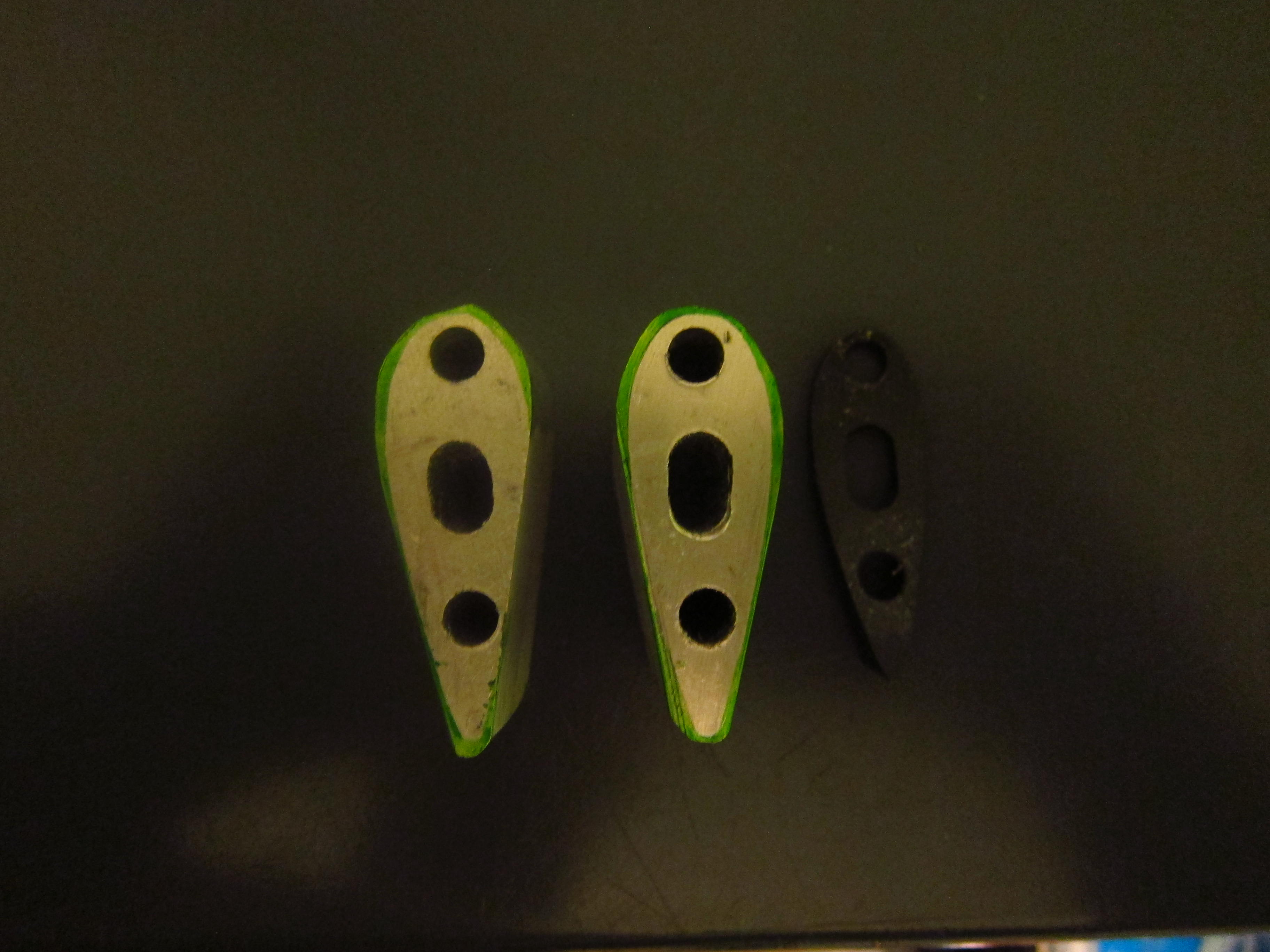
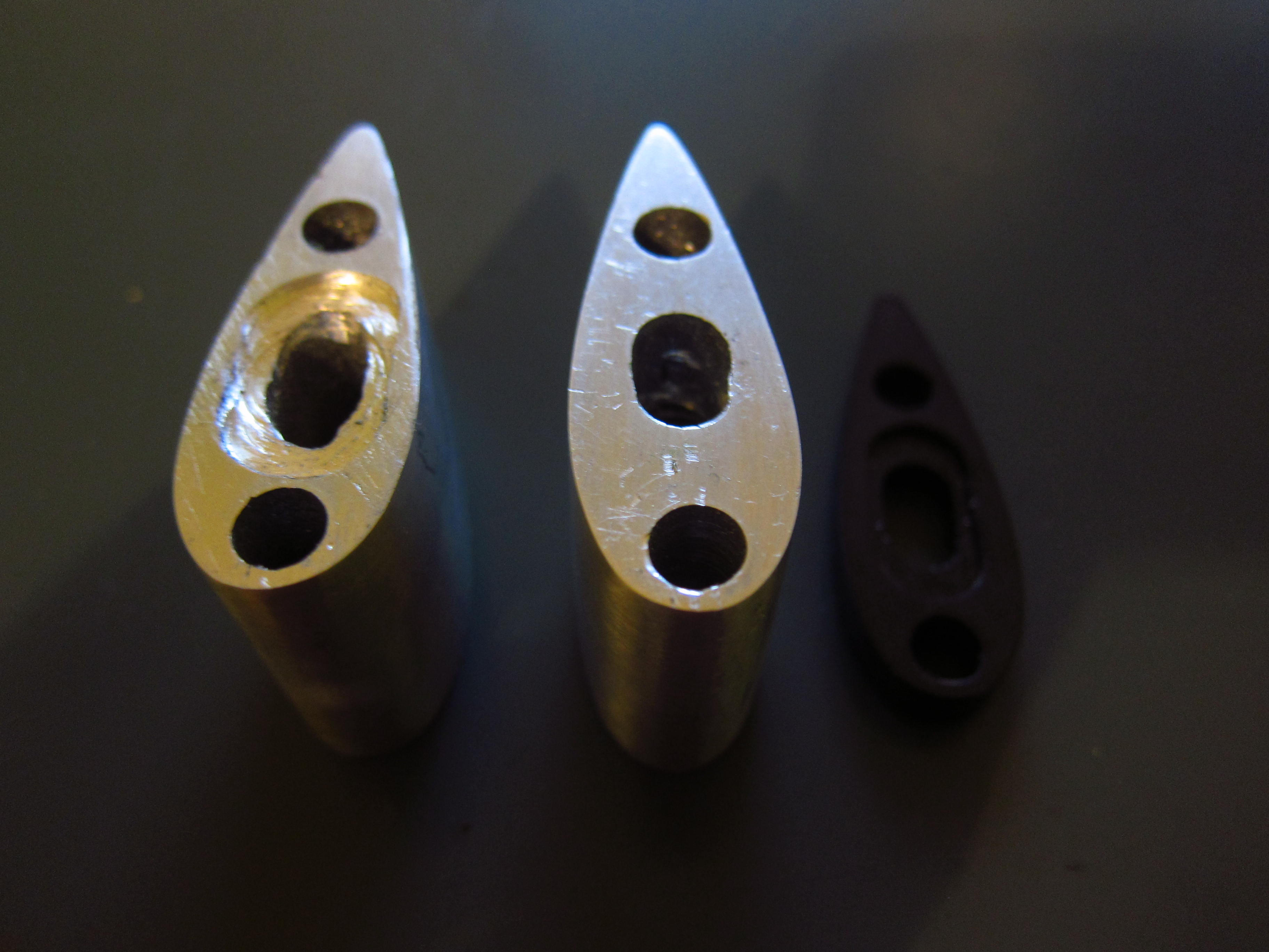
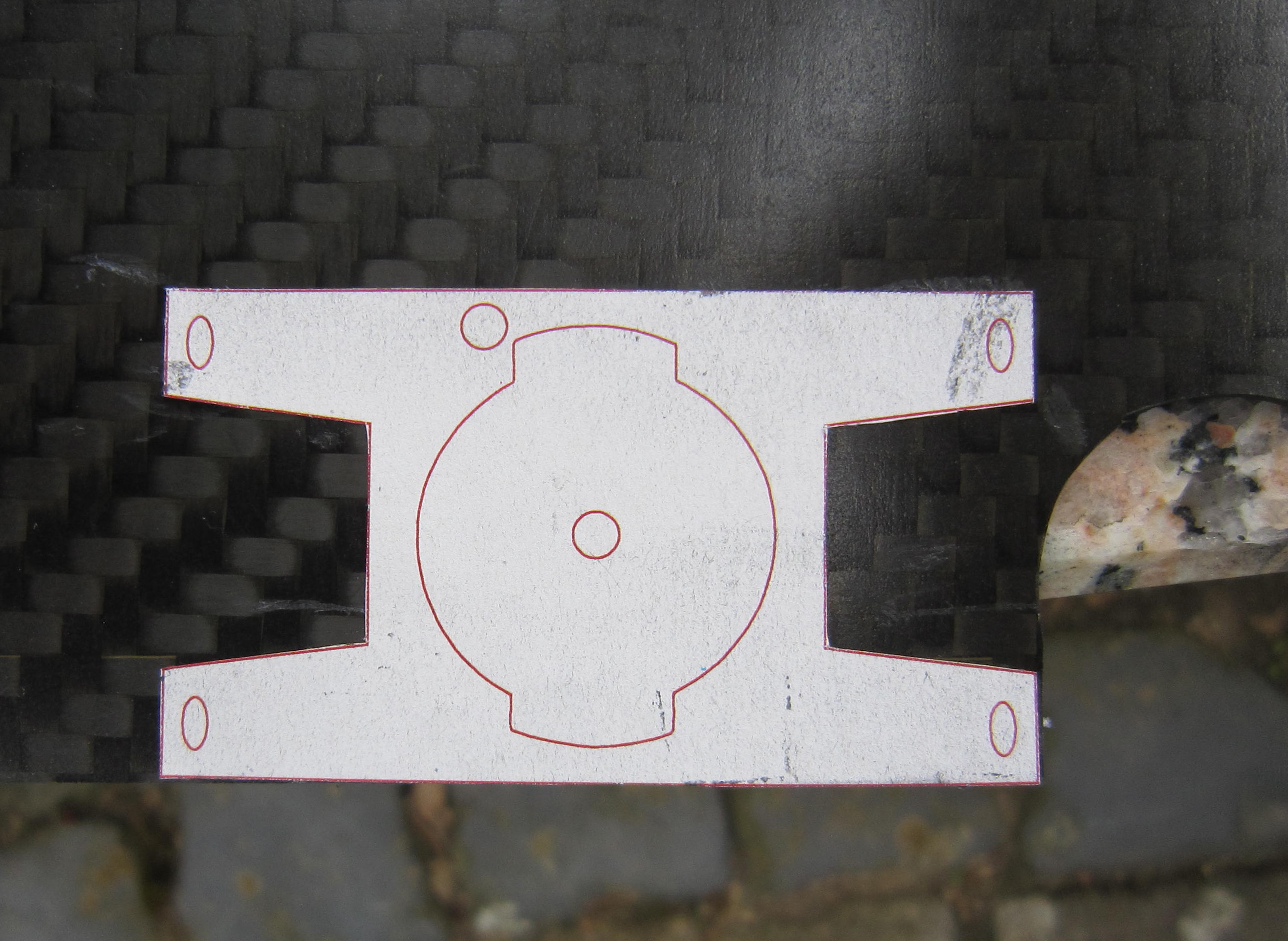
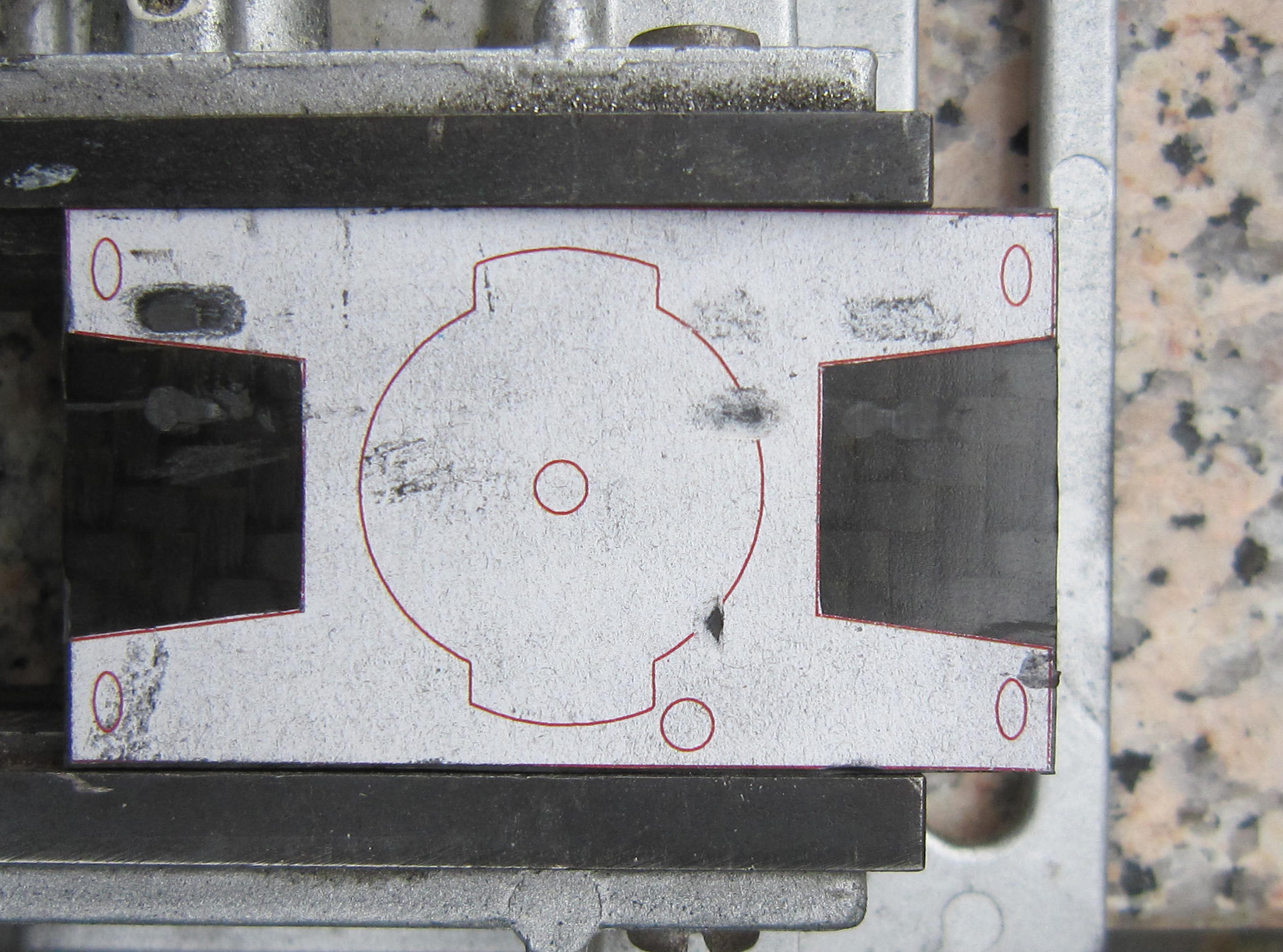
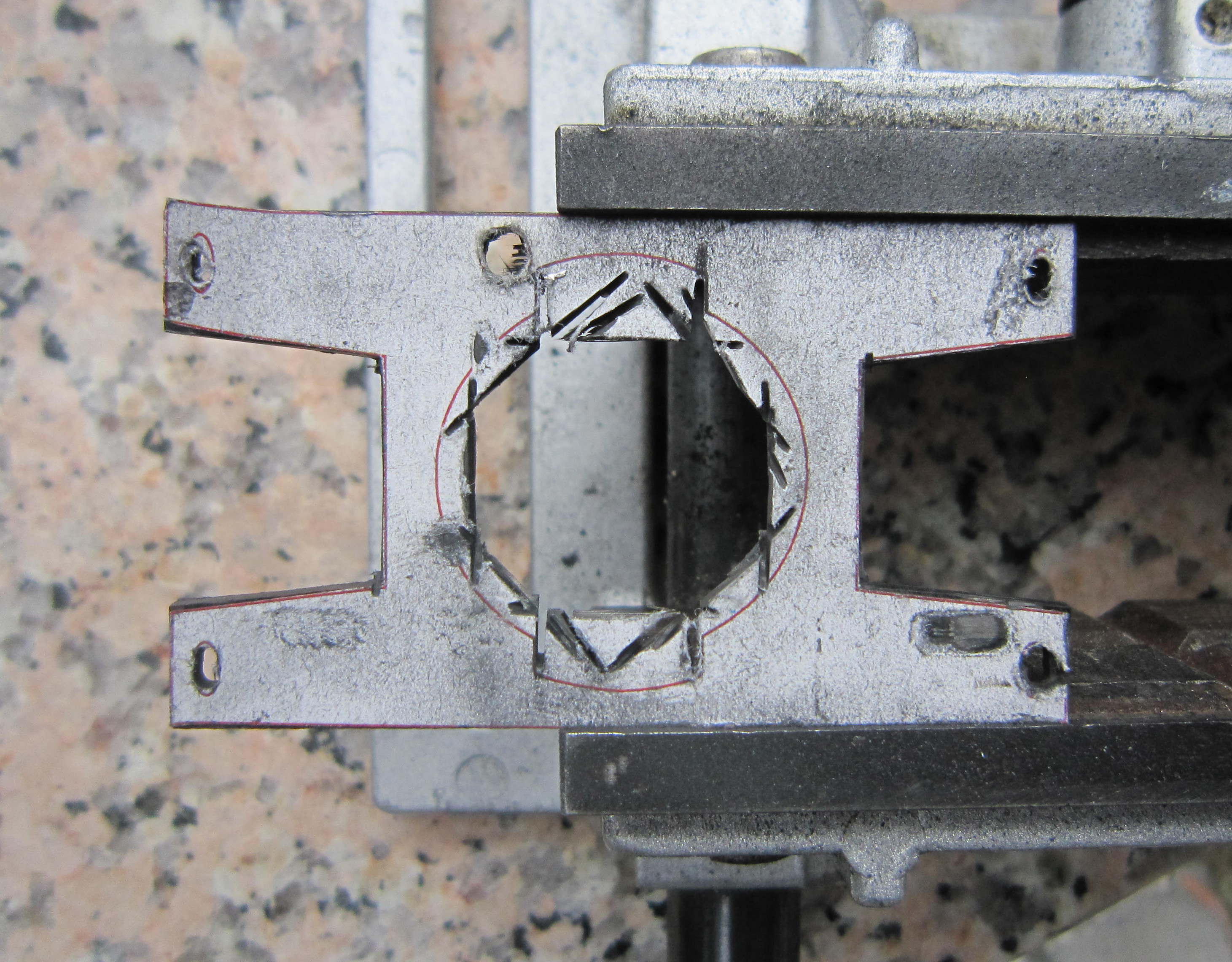
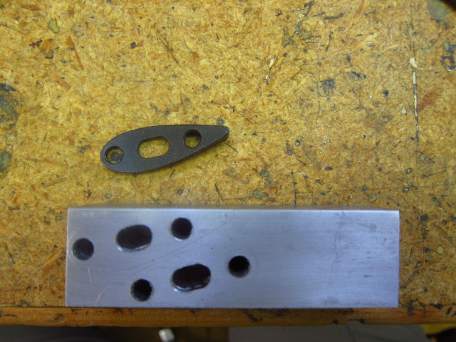
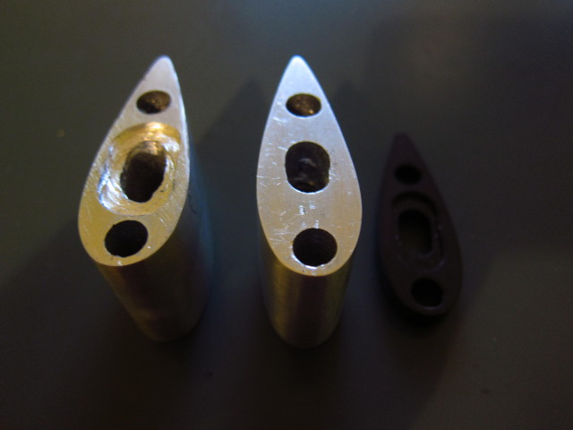
After a few short test rides of about 65k, I realized that the position on the extensions is about 2cm too low when using only the stock spacers. So I decided to build two spacers on my own. I transferred the contour of a spacer to a solid block of aluminium and drilled the holes first.

20131024_Scott-Plasma-TT_63

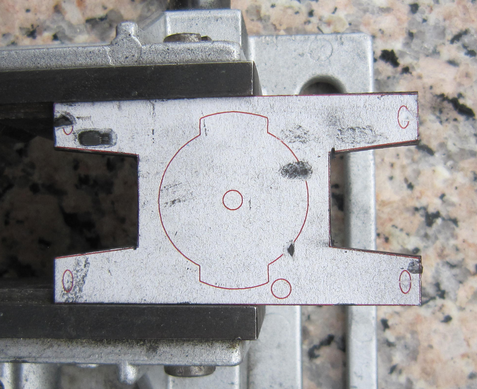
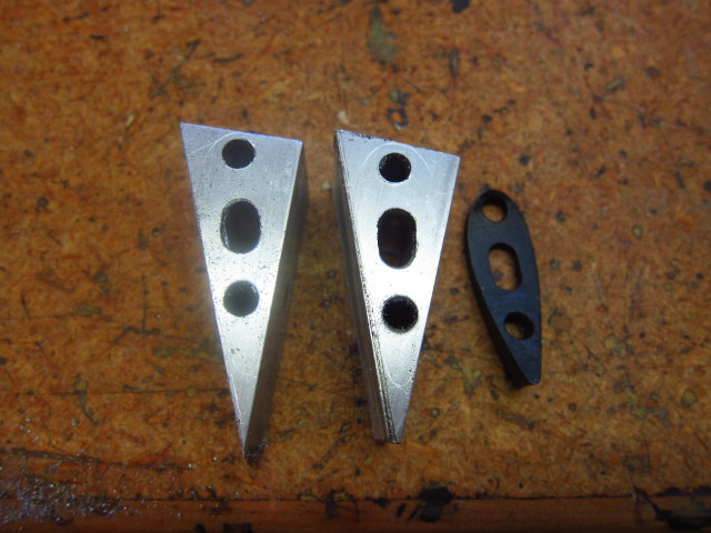
Afterwards, I used a saw to cut the block into the rough outer dimensions.

20131024_Scott-Plasma-TT_64

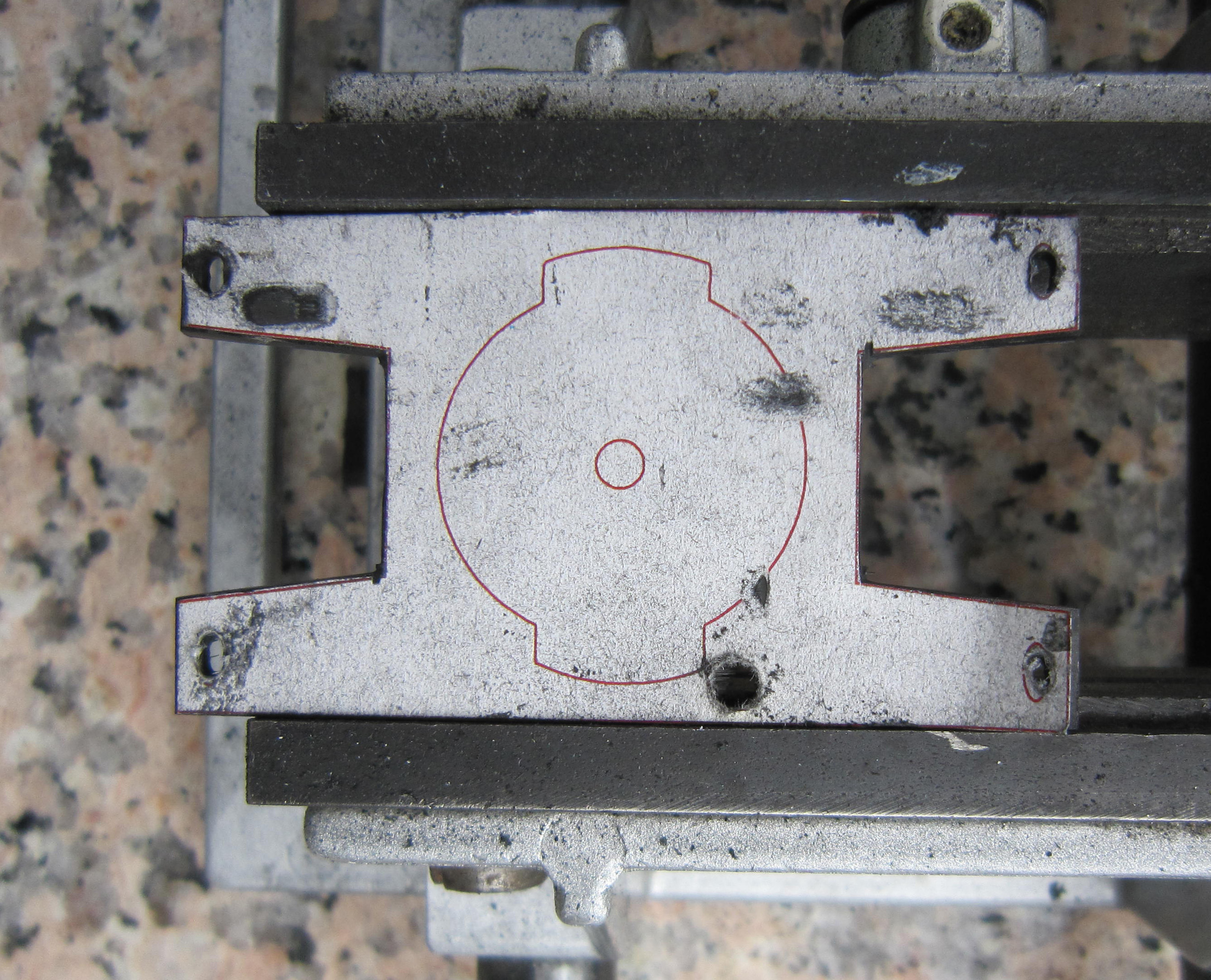
The preliminary result looked like that.

20131024_Scott-Plasma-TT_65

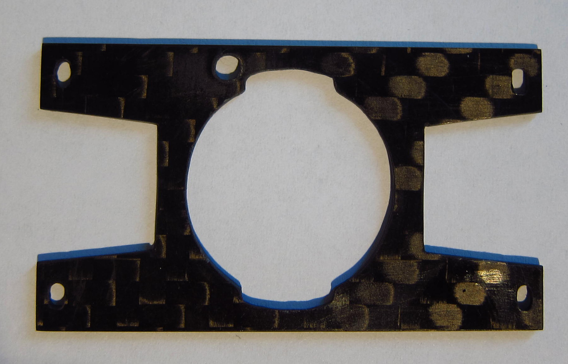
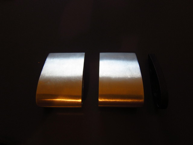
After some filing, the spacers looked a bit more like the desired result.

20131024_Scott-Plasma-TT_66

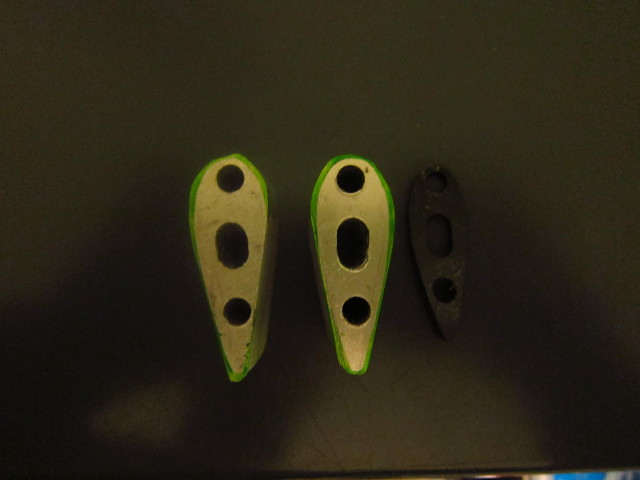
And after some more filing, the work was done.
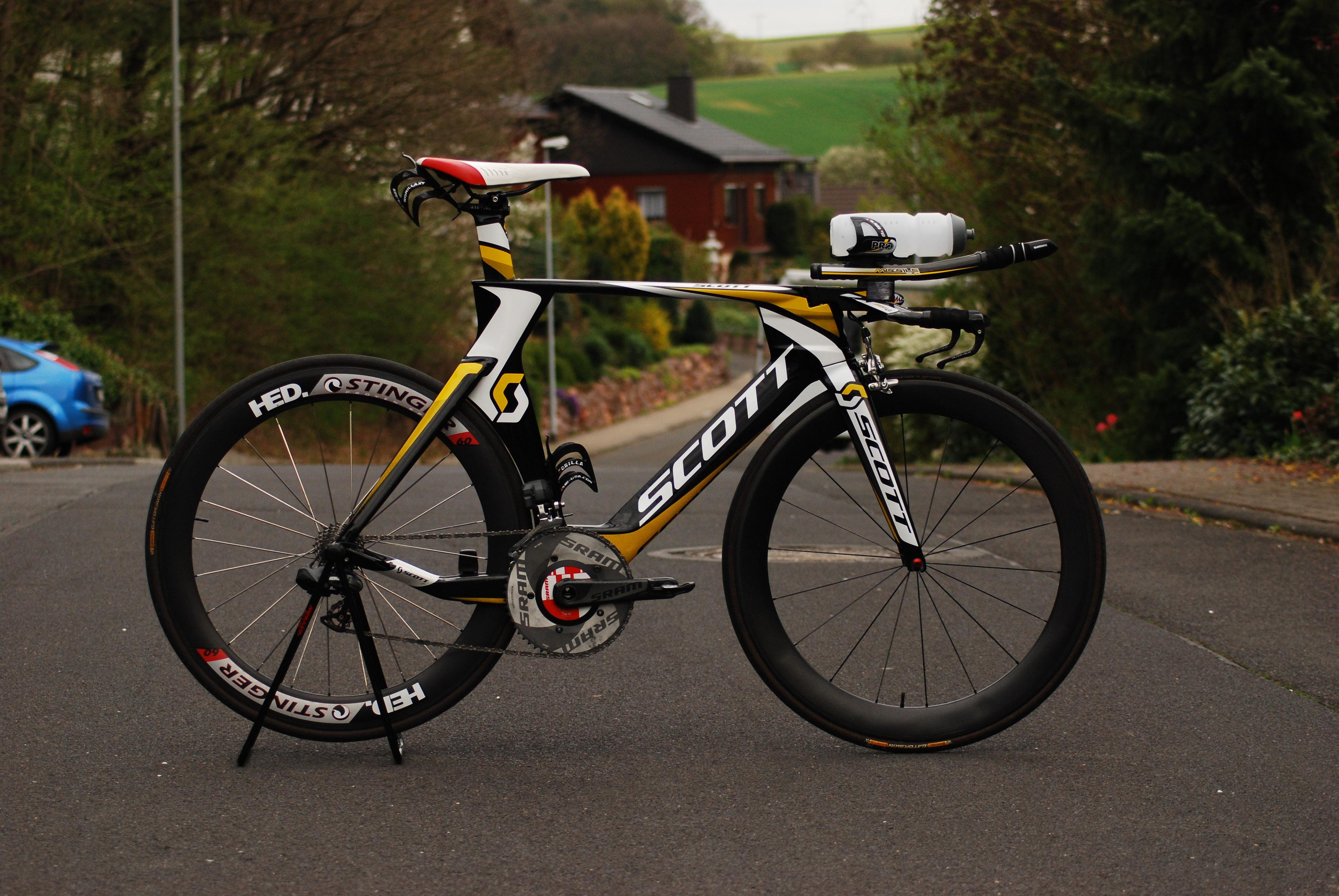
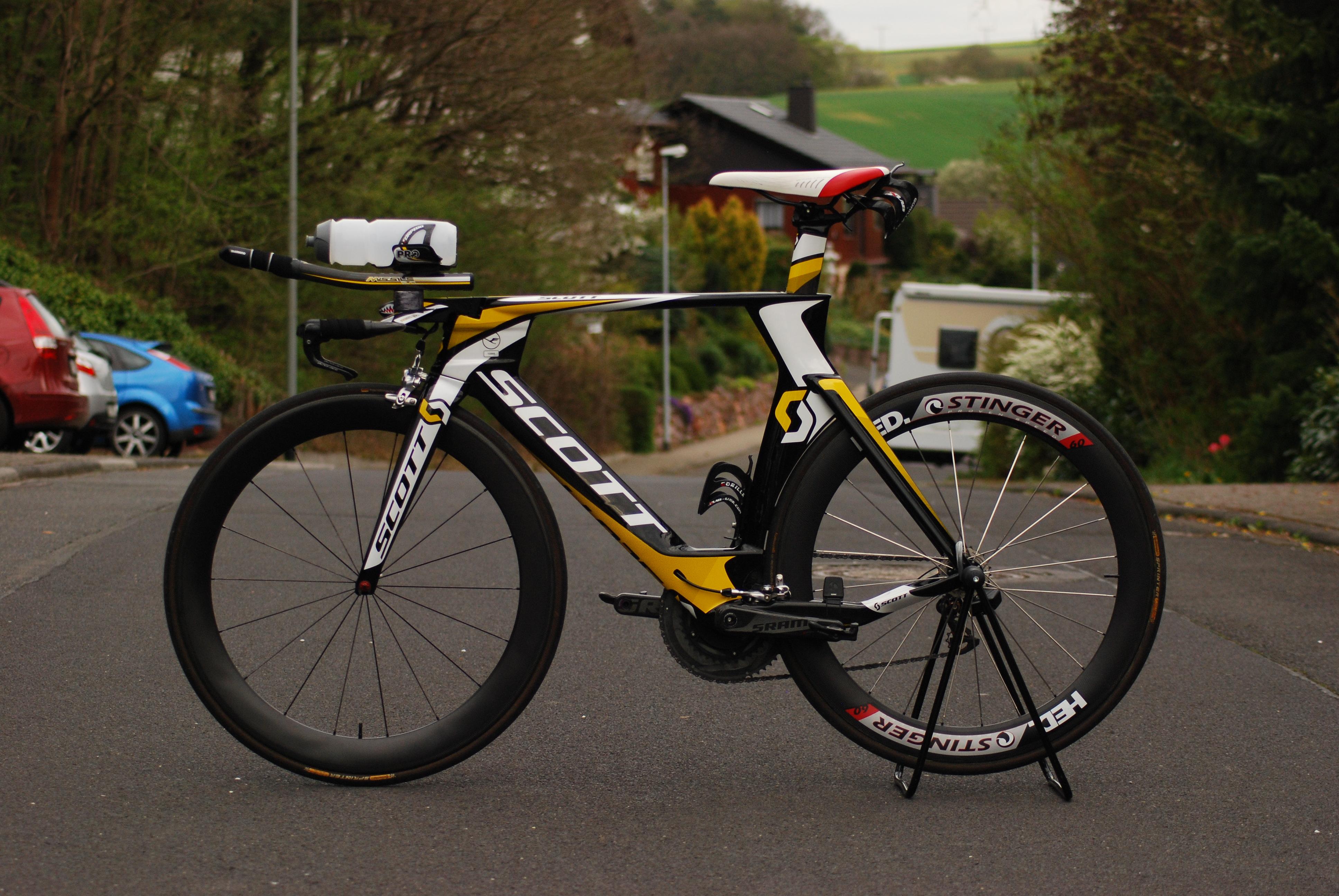
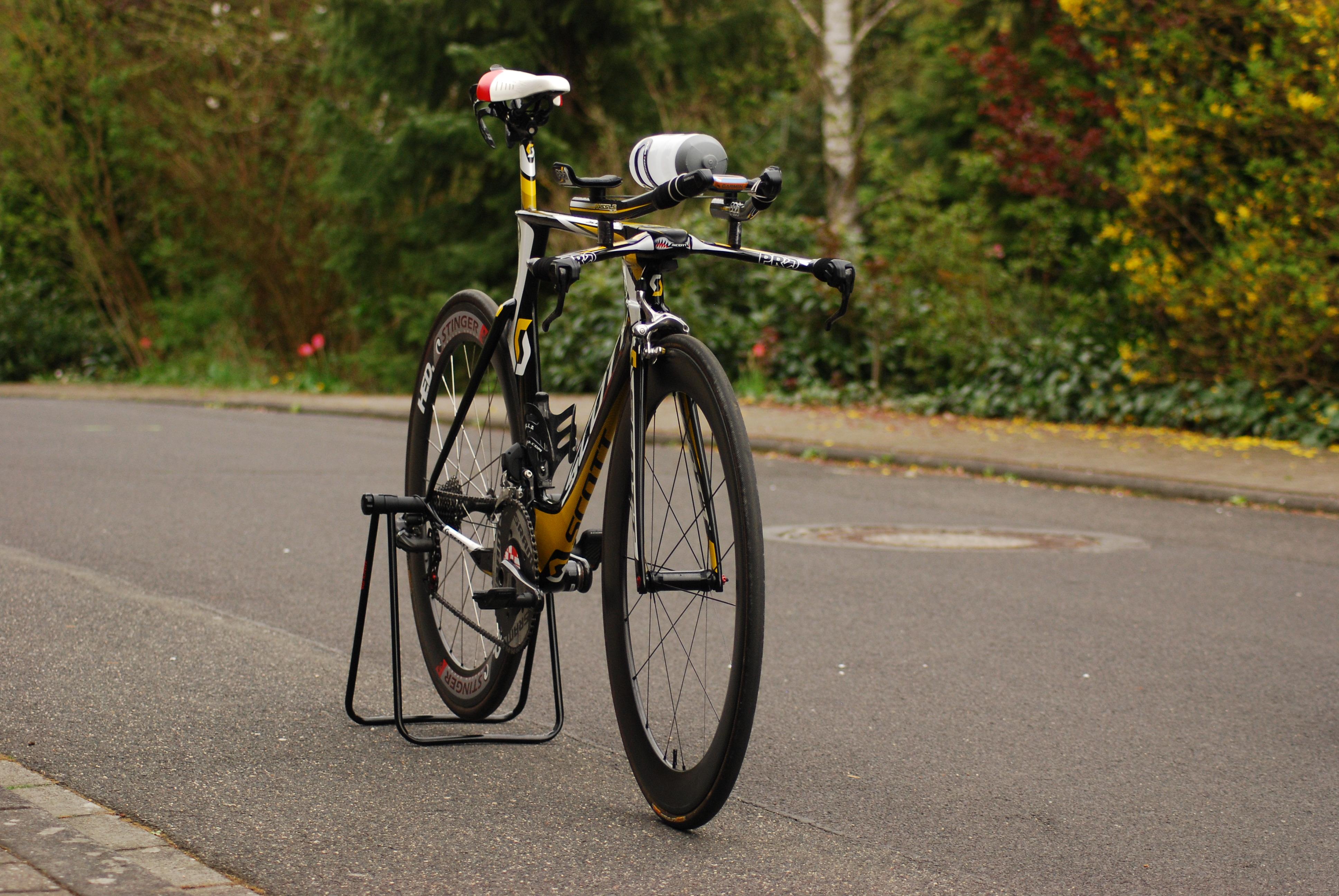
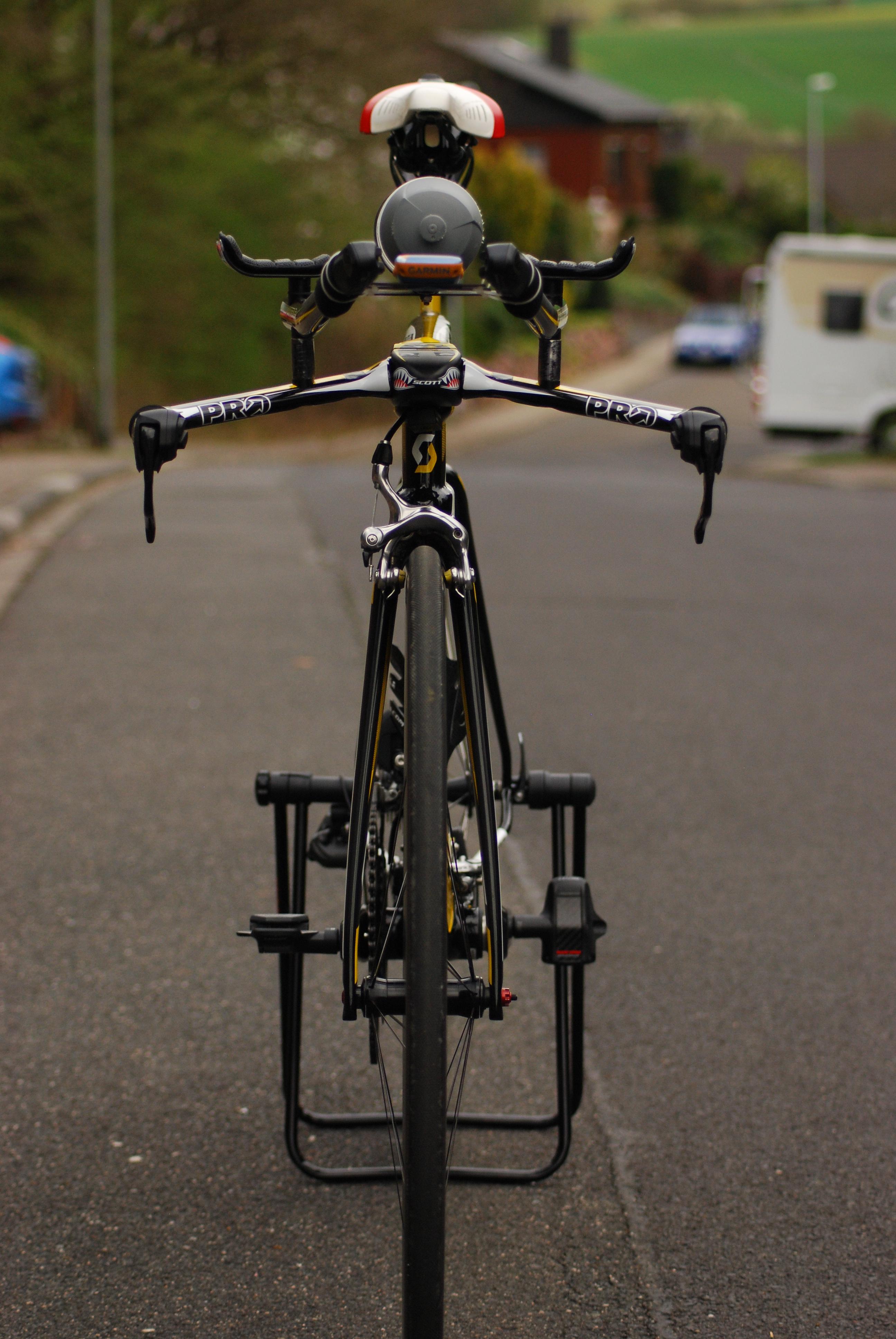
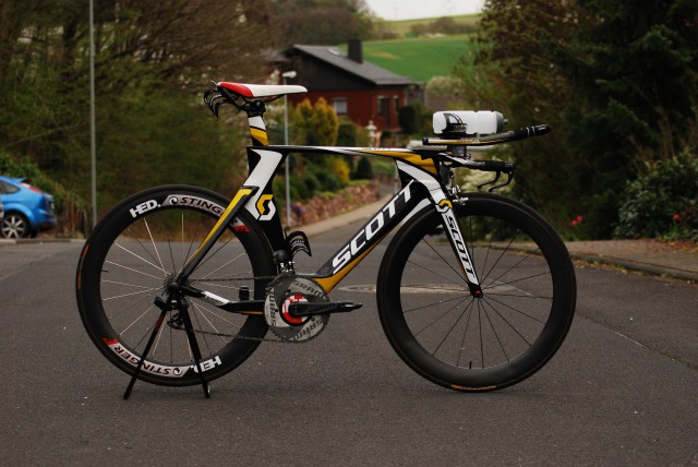
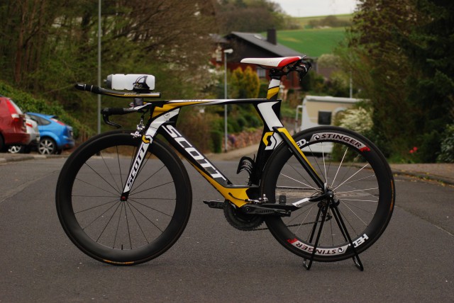
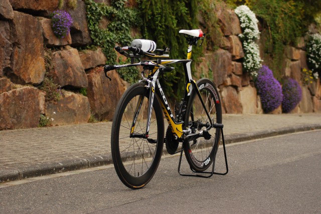
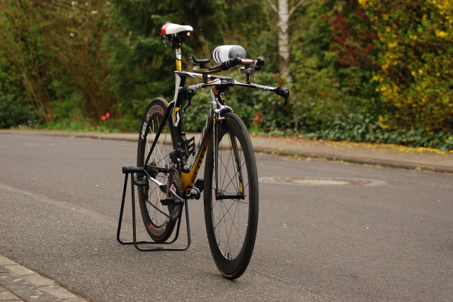
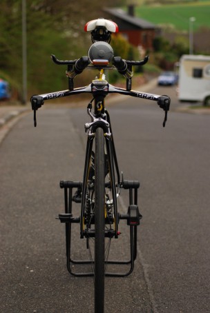
20131024_Scott-Plasma-TT_67

20131024_Scott-Plasma-TT_68

Completed Build

The completed build looks like this:

Ride Impressions

I will add more to this section later – some first impressions.

  • Electronic shifting is fantastic – especially on a tri bike, it is a great improvement to be able to shift with hands on bull horns.
  • Very stiff frame.
  • Brakes act quite aggressive and are reliable.
  • Position on base bar is quite low.
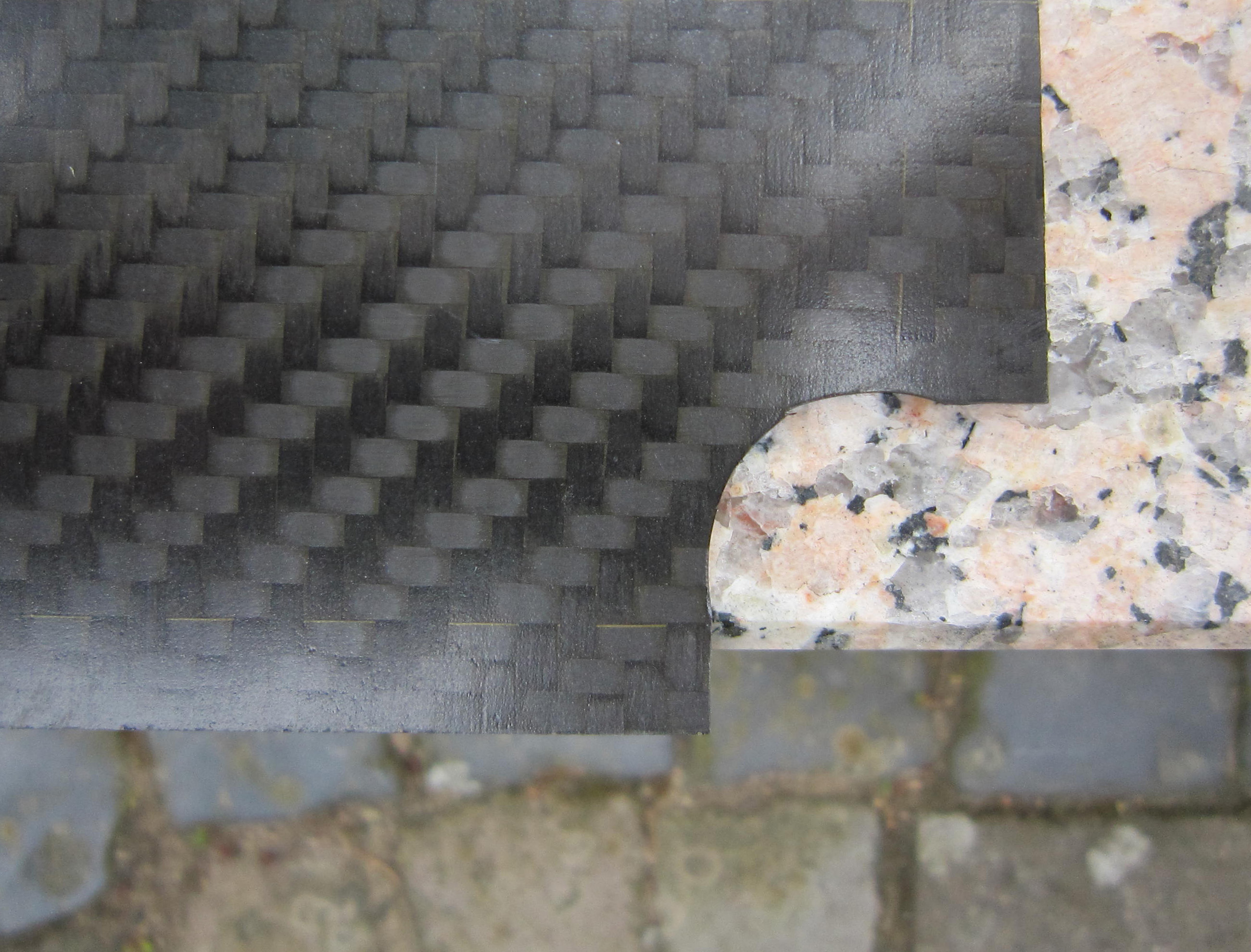
  • Carbon extensions and basebars are comfortable while riding in the cold: Don’t suck temperature out of the fingers as much as aluminium bars.

Performance

The route I currently ride most frequently is from my office at Frankfurt Airport through the Taunus to Limburg. The route is 62,3km long and has an elevation gain of roughly 420 meters, net elevation gain is about 30 meters.

I would say I am satisfied with the improvement that is for sure not only due to better outside conditions like tailwind and such. The bike doesn’t just look fast, it is fast!

Reviews

Specification Scott Plasma TT

Frame Scott Plasma TT 1.426g
Fork Scott Plasma TT 408g
Headset Ritchey WCS 50g
Rear Derailleur Shimano Ultegra Di2, RD-6770 271g
Front Derailleur Shimano Ultegra Di2, FD-6770 166g
Battery Shimano Di2 SM-BTR2, intern 50g
Junction Box Front: Shimano SM-EW90-A; Rear: Shimano SM-JC41 12g
Extension Shifters Shimano Ultegra Di2, SW-R671 101g
Di2 Cables 1x 500mm RD to JC41, 1x 250mm FD to JC41, 1x 250mm Battery to JC41, 1x 950mm JC41 to SM-EW90 18g
Brake Levers Shimano DuraAce Di2, ST-9071 125g
Brakes Shimano DuraAce, BR-7800 320g
Cassette Shimano Ultegra CS-6700: 11-23 (Race), 11-27, 12-25 (Training) 203g
Wheels – Race Vorderrad: HED Stinger 6; Hinterrad: HED Stinger 60 1.423g
Wheels – Training Shimano WH-RS80-C24-CL 1.460g
Tires – Race Continental Sprinter Gatorskin 544g
Tires – Training Continental Grand Prix GP4000s 602g
Crank SRM SRAM S975 GXP, 175mm 891g
Chainrings SRAM Aero, 55/39 (Race), SRAM Red, 53/39 (Training) g
Bottom Bracket SRAM Truvativ BB86 Pressfit 80g
Stem Scott Plasma TT 451g
Aerobar PRO Missile Evo 681g
Saddle ISM Adamo Time Trial 276g
Seatpost Scott Plasma TT 258g
Pedals Look Keo Classic 341g
Frame Size 54 cm
Weight (ready to ride) 8.640g

Endurance Test: Garmin compatible bike mount for Sony Xperia active

About 14 months ago, I published a post regarding a custom made Garmin compatible bike mount for my Sony Xperia active. In fact, this solution works for every smartphone if you feel comfortable to glue two plastic discs to the back of your phone. Therefore, I would recommend to apply this solution only to smartphones which have a replaceable back cover.

How has this mount performed in real life usage? In one sentence: It has never let me down! Neither did the mount come off the back cover nor did it work itself free. I have used it for about 700km on our Chariot Cougar, 600km on my travel bike and 1.800km on my triathlon bike. There were some brutal pot holes on this ride – the phone stuck to my bar like it was glued directly onto it.

20130630_Xperia-Active_On-Travel-BikeOn my travel bike, I usually only use the Sony Xperia active displaying the route that I want to follow. The IpBike-App of Ifor Powell is perfect for that matter.


20130630_Xperia-Active_On-Triathlon-Bike_220130630_Xperia-Active_On-Triathlon-Bike_3On my triathlon bike, I usually have the Garmin Edge mounted between my extensions to display power and cadence data. The Xperia active sits on the basebar displaying map and route, again using the IpBike App recording all sensor data via ANT+.


20130630_Xperia-Active_On-Triathlon-Bike_4I was asked whether the phone would work itself free due to the missing locking tangs. It did not. You have to make sure that the thickness of the plastic disc glued to the back cover matches the thickness of the original Garmin mount as precisely as possible. This will ensure that there is a tight fit. If you cannot get a platter with a thickness of precisely 1.45mm, get a slightly thinner one – the fit will be even more tight.

And actually, it is an advantage to forgo the locking tangs because you can turn the smartphone to any position and are not limited to a 90° turn. On the picture to the left, you can see a scenario in which this is important.

Reiserad goes Electric – Auf- und Einbau eines Ladegeräts

Ende Mai werden wir eine Familien-Radtour von Limburg nach Rotterdam machen. Eine Gesamtstrecke von knapp 600km kann man natürlich nicht ganz ohne Navigations-Unterstützung zurücklegen. Eine konventionelle Papier-Karte empfinde ich aber für diesen Zweck als nicht mehr zeitgemäß – zu sperrig und zu wetterempfindlich. Schließlich bringt ein handelsübliches Smartphone heute schon alles mit, was man zur Fahrrad-Navigation benötigt: Eingebautes GPS, ein helles Display, ANT+-Unterstützung zur Kopplung der Fahrradsensoren und dann noch ein entsprechendes App zur Kartendarstellung. Einziger Haken bei der Verwendung von Smartphones: Nach ca. 4,5h GPS- und Display-Nutzung ist der Akku leer. Bei geplanten Tagesetappen von fünf bis sechs Stunden ist die Stromversorgung unterwegs also ein Problem.

Die meisten Reiseräder haben zur Stromversorgung der Lichtanlage einen Nabendynamo im Vorderrad – so auch mein Reiserad. Nach etwas Recherche im Internet fanden sich verschiedene verfügbare Produkte, die sich in Form einer Gleichspannungsquelle zwischen Nabendynamo und Lichtanlage schalten lassen, z.B. das E-Werk von Busch & Müller. Wenn die Lichtanlage angeschaltet ist, schaltet sich die Spannungsquelle ab. Wenn die Lichtanlage ausgeschaltet ist, kann die Spannungsquelle angeschlossene Verbraucher mit Strom versorgen. Zusätzlich lässt sich die Spannungsquelle um einen Pufferakku erweitern, sodass angeschlossene Verbraucher auch während Pausen bzw. während Einsatz der Lichtanlage versorgt werden können. Einzige Nachteile der bereits verfügbaren Produkte:

  • Nur bedingt zum versteckten Einbau geeignet
  • Kapazität der verfügbaren Pufferakkus überschaubar
  • Hoher Preis

Nach etwas weiterer Recherche im Internet bin ich auf das Projekt „Forumslader“ aufmerksam geworden. Hier wurde mit massivem privaten Einsatz eine Reihe unterschiedlicher Schaltungen entwickelt, die die oben genannten Nachteile kommerzieller Produkte beseitigen und zusätzlich noch eine höhere Energieausbeute und -effizienz aufweisen. Nach eingehender Analyse habe ich mich für den „4-Fach-Forumslader Automatik“ entschieden, dieser ist für den versteckten Einbau im Steuerrohr ausgelegt. Als Pufferakkus habe ich drei Zellen vom Typ 18650 LiMn von Sony ausgewählt, sodass ich auf eine Speicherkapazität von ca. 25 Wh komme – das sollte für einige Smartphone-Ladungen ausreichen. Der Forumslader erzeugt abhängig von der Fahrtgeschwindigkeit auf einer Fahrtstrecke von 100km zwischen 20 und 30 Wh – das Smartphone verbraucht während einer solchen Fahrtstrecke ca. 4,5 Wh, sodass ein deutlicher Energieüberschuss zur Ladung der Pufferakkus bzw. anderer Verbraucher verbleibt.

Nach meiner Bestellung des Bausatzes hatte ich zwei Tage später den Bausatz auf meinem Schreibtisch. Die Platine ist weitgehend vorbestückt, alle SMD-Bauelemente sind vorbestückt und verlötet. So blieb für mich nur noch übrig, einige Transistoren und die Kabel zu bestücken. Dazu konnte ich der gut bebilderten Schritt-für-Schritt Anleitung folgen, die keine Fragen offen ließ.

Laut der Internetseite des Forumslader-Projekts sind für den komplett versteckten Einbau im Steuerrohr nur Akkus vom Typ „18350“, die etwas mehr als halb so lang sind wie die von mir verwendeten Zellen vom Typ „18650“. Da mein Reiserad aufgrund der 26“-Laufräder ein sehr langes Steuerrohr hat, nahm ich mir die Zeit, um genau auszumessen, ob ich nicht doch die komplette Schaltung inklusive Pufferakku im Steuerrohr „verstecken“ kann. Und siehe da: Die Länge von Platine zuzüglich drei Zellen vom Typ 18650 zuzüglich eines Überstandes zum wasserdichten Versiegeln liegt bei 295 mm. Die Länge des Steuerrohrs, gemessen von der Unterseite der Ahead-Kralle bis zur Schraube durch die Gabel, an der das Schutzblech befestigt ist, liegt bei 297 mm – perfekt!

Die Kabel habe ich der guten Ordnung halber mit Tesafilm an den Akkus befestigt.

Hier das Bild der fertig aufgebauten Schaltung, mit Schrumpfschlauch überzogen und an den Enden mit Heißkleber versiegelt. Für den Aufbau habe ich soweit ca. 1,5h benötigt.

Damit die Schaltung im Steuerrohr noch etwas stärker gegen Schäden durch Stöße bzw. Vibrationen geschützt ist, habe ich von außen auf den Schrumpfschlauch Moosgummi-Streifen aufgeklebt.

Die komplette Schaltung inkl. Kabel wiegt 181 g.

Nun blieb noch zu erledigen, die vom Forumslader erzeugte Energie auch für Verbraucher zugänglich zu machen. Als eleganteste Lösung erschien es mir, eine USB-Buchse in einen Spacer einzubauen.

Also nahm ich einen handelsüblichen 20mm-Alu-Spacer…

und zeichnete im oberen Drittel ein „Einbaufenster“ von 14 x 5,5 mm ein.

Dieses Fenster habe ich mit zwei Bohrungen geöffnet…

und anschließend ausgefeilt.

Auf der gegenüberliegenden Seite habe ich noch ein Loch zum Einbau der Status-LED gebohrt.

Sowohl die LED als auch die USB-Buchse habe ich anschließend mit 2K-Epoxidharzkleber mit dem Spacer verklebt. Nun sollte der Spacer grundsätzlich abnehmbar sein, falls man mal die Gabel ausbauen muss. Daher konnte ich die notwendigen Kabel vom Forumslader nicht direkt an LED und USB-Buchse anlöten, sondern musste eine Steckverbindung im Spacer vorsehen. Dazu habe ich Pfosten-Steckverbinder verwendet, die man normalerweise zur Bestückung von Platinen verwendet. Diesen Steckverbinder habe ich mit Heißkleber am Spacer fixiert.

Da die USB-Buchse nur 2mm unterhalb der Oberkante des Spacers eingebaut ist, musste ich die Top Cap des Steuersatzes etwas nachbearbeiten.

Nun war noch die Verbindung zwischen Forumslader und Spacer herzustellen. Ich wollte keine spezielle Ahead-Kralle verwenden, sondern falls möglich meine bestehende Kralle verwenden. Zunächst habe ich zwei Kabel von oben nach unten durch die Kralle gesteckt.

Danach habe ich ein vieradriges Flachbandkabel, aufgeteilt in jeweils zwei Adern, vorbereitet und…

…an das untere Ende der durchgeschobenen Kabel gelötet.

Dann konnte ich das Flachbandkabel von oben durch die Ahead-Kralle ziehen…

…und die angelöteten Kabel wieder entfernen.

Am Kabelende zum Spacer hin habe ich eine Pfostenstecker-Buchse angebracht. So kann kein ungewollter Kurzschluss entstehen, wenn der Stecker vom Spacer getrennt ist.

Fertig angeschlossen sieht der Spacer dann so aus:

Am Kabelende zum Forumslader habe ich einen Pfostenstecker verwendet, wie er zum Anschluss von Lautsprechern an Computer-Mainboards verwendet wird.

Nun habe ich den Forumslader in das Steuerrohr geschoben.

Die Längenberechnung ging auf – nur noch die Verbindungskabel schauen heraus. Nun habe ich alle Steckverbinder miteinander verbunden.

Ich konnte ohne zu quetschen die Schraube zur Befestigung des Schutzbleches wieder anbringen. Nach dem Einbau ist nur noch ein kleines Kabelbündel vom Forumslader zu sehen.

Jetzt war es Zeit für einen Funktionstest. Ich habe wie in der Anleitung beschrieben das Vorderrad angedreht – die Status-LED im Spacer begann zu blinken, also alles ok.

Damit die USB-Buchse bei nicht-Benutzung besser gegen Oxidation, Wasser und Staub geschützt ist, habe ich noch eine Gummi-Staubkappe aufgesteckt.

Am nächsten Tag dann die erste etwas längere Testfahrt.

Losgefahren bin ich laut Status-LED mit einem Akkufüllstand zwischen 0 – 33%. Nach 40km Fahrt inkl. Ladung des Smartphones war der Akku laut LED bei einem Füllstand zwischen 66 – 100% angekommen. Wahrscheinlich lag der Ladestand also vor Abfahrt nahe an 30% und nach der Fahrt nahe bei der 70%.

In Summe hat der Forumslader bislang super funktioniert, die Gesamtkosten des Projekts lagen bei ca. 130 €. Der erste richtige Härtetest erfolgt dann bei unserer Tour nach Rotterdam – dann gibt es ein Update dieses Blogs. Einstweilen möchte ich mich herzlich bei Jens During für die Entwicklung und Fertigung des Forumsladers sowie den Support bedanken! Das ist wirklich ein tolles Projekt, um so bemerkenswerter, dass der aktuell erreichte Grad an Professionalität bislang „non-kommerziell“ ist.

Improved version: Aerobar Computer Mount for Garmin Edge

About one year ago, I published a post about a custom aerobar computer mount for the Garmin quarter turn mount.

After using it for one year, I was satisfied with the solution except for one thing: The computer used to tilt forward while riding due to the fact that I did use only one zip tie on each side. To fix this, I manufactured an improved design over the weekend which employs two zip ties on each side.

It starts with a plate of nude carbon with a thinkness of 1.4mm.

I printed out the layout of the computer mount and glued it onto the carbon plate.

Using a Proxxon cutting machine, first I cut out the outer shape.

After that, I cut out the inner recessions on both sides.

Next, I drilled four holes for the zip ties and one more hole to keep the barometric sensor uncovered.

As the last cutting step, I roughly cut out the inner shape of the Garmin mount.

After some filing, the final result looked like this:

Contrary to the previous version, I don’t need the original Garmin mount any more – hence no gluing involved. The Garmin Edge series directly mounts into the carbon plate. From the back, it looks like that:

The total weight including for zip ties is 3g – this is 4g less than the original Garmin mount.

Mounted to the extensions, the holder looks like that. The next time I’ll renew the bar wrap I’ll hide the zip ties beneath the wrap.

Garmin Edge 500 mounted to the extensions and ready to display some serious power numbers ;-).

The computer is sitting flush to the extensions.

I am quite sure that the tilting issue is fixed by this new and improved version.

Rennradgepäckträger Tubus Fly Edelstahl

Mein Reiserad für lange Touren mit schwerem Gepäck habe ich mit einem “Tubus Cargo Evo” Gepäckträger aufgebaut. Für eine schnelle Alpenüberquerung mit ordentlich Höhenmetern ist das allerdings nicht das optimale Rad – ein Rennrad ist für diese Tour die bessere Wahl. Wo aber das Gepäck für eine Mehrtages-Tour verstauen? Ein Rucksack erscheint mir weniger geeignet – also muss ein Gepäckträger an das Rennrad. Die Herausforderung ist nur, dass die wenigsten Rennräder passende Montagevorrichtungen haben.

Montage:

Nach längerer Suche habe ich mich dann für den “Tubus Fly” Gepäckträger aus Edelstahl entschieden. Die beiden unteren Befestigungspunkte an den Füßen des Gepäckträgers müssen nicht mit dem Rahmen verschraubt werden, sondern können über eine als Zubehör erhältliche Fußverlängerung direkt an der Achse mit einem verlängerten Schnellspanner befestigt werden. Der obere Befestigungspunkt wird mittels einer Aluminium-Strebe an einem Winkel zwischen Hinterradbremse und dem dafür vorgesehenen Querträger am Hinterbau angebracht.

Das Endergebnis sieht dann so aus:

Dieser Winkel wird zwischen Querstrebe und Hinterradbremse montiert – bei Carbonrahmen ist es sicherlich empfehlenswert, ein dünnes Gummiplättchen zwischen Winkel und Querstrebe einzusetzen.

Die Aluminiumstange muss man noch entsprechend biegen.

Die Füße des Trägers werden mit einem Abstandshalter auf den Schnellspanner geschoben.

Der Träger ist für eine maximale Last von 18kg freigegeben. Das ist meines Erachtens völlig ausreichend – mein Packsack für die Transalp wird ca. 3,5kg wiegen.

Praxisbericht:

Ende August 2013 bin ich mit Rennrad und dem Tubus Fly Gepäckträger zu einer Alpenüberquerung aufgebrochen (https://www.frankbauer.net/blog/tag/transalp-2013/). Mein Gepäck von habe ich in einem Ortlieb Packsack verstaut und mit einem Spanngurt von Tubus am Gepäckträger befestigt. Das Fahr- und Lenkverhalten des Rades hat sich durch die etwas veränderte Gewichtsverteilung für mich nicht spürbar verändert. Die Befestigung des Gepäcks ist mit dem auf den Rohrdurchmesser abgestimmten Spanngurt von Tubus sehr einfach und sicher. Auch bei schnellen Abfahrten und schlechter Straße hat sich das Gepäck nicht verschoben. Die Edelstahl-Version des Tubus Fly ist nicht pulverbeschichtet – daher reibt sich jedoch auch keine Beschichtung ab und die Oberfläche bleibt dauerhaft unverkratzt.

Zusammenfassung:

Ich bin mit dem Tubus Fly Edelstahl sehr zufrieden. Die Montage ist problemlos und schnell durchführbar. Das Gepäck nicht in einem Rucksack zu transportieren ist meines Erachtens eine deutliche Erleichterung, da sich am Rücken weniger Wärme staut und die Schultern nicht beansprucht werden. In Summe kann ich diese Lösung nur weiterempfehlen.

Links: